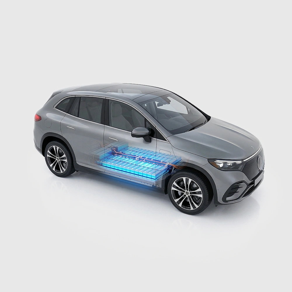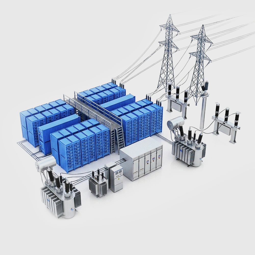
Does 10C mean a full charge in five minutes?
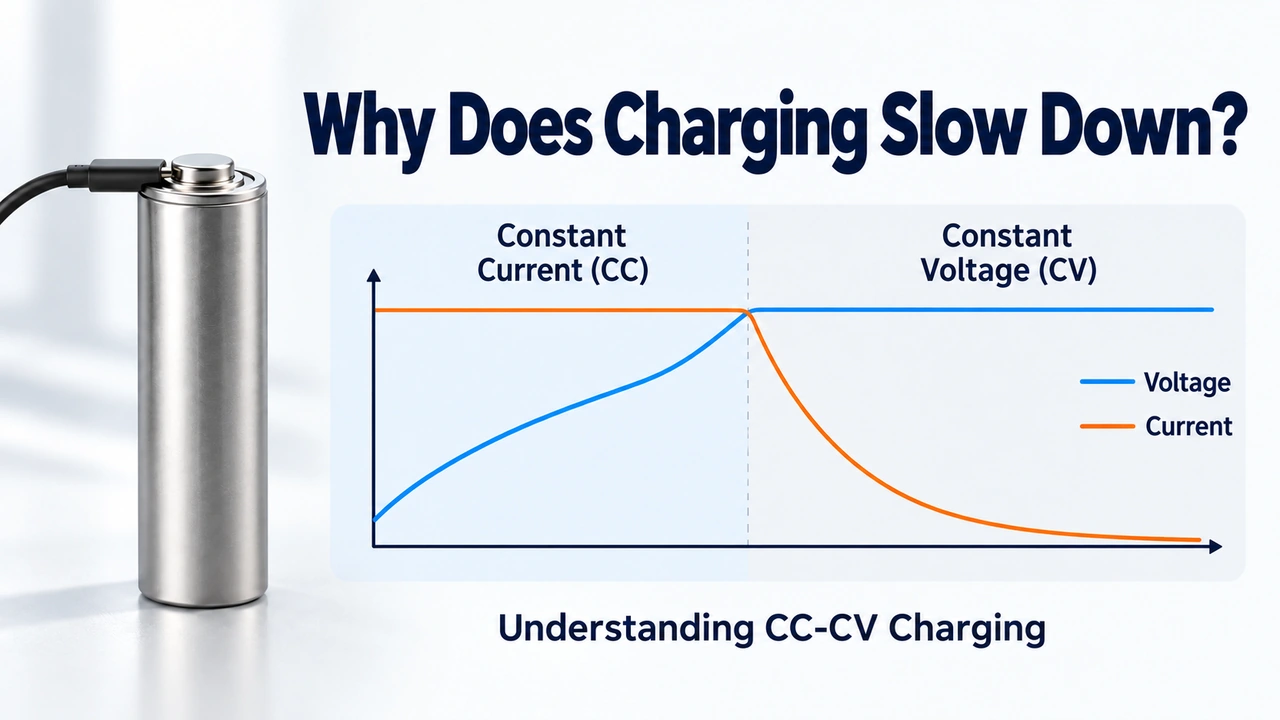
C-rate expresses charge or discharge current relative to rated capacity. Under ideal constant-current conditions, 1C corresponds to approximately 60 minutes and 10C to approximately 6 minutes. Real batteries, however, are commonly charged using a constant-current, constant-voltage (CC-CV) profile, with current tapering as the battery approaches a high SOC. Cables, connectors, chargers, the battery management system (BMS), and thermal management also limit the power that a vehicle can accept continuously. A "five-minute charge" therefore usually means adding a specified amount of energy within a defined SOC window, not charging from 0% to 100% at any temperature.
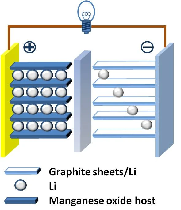
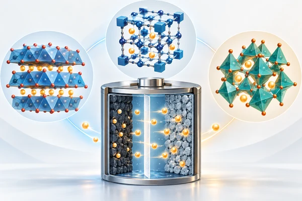
Figure 1. During charging, lithium ions move through the electrolyte while electrons travel through the external circuit.
A 2026 analysis by the International Energy Agency (IEA) notes that some of the latest battery technologies can reach 10C or 12C during the early stage of charging. Combined with battery platforms above 800 V and high-current charging systems, this has brought passenger vehicles close to megawatt-scale charging. The IEA also emphasizes that these high C-rates occur mainly at the beginning of charging, while infrastructure reliability and peak grid demand remain important constraints on large-scale deployment [1]. Any evaluation of ultra-fast charging should report the initial and final SOC, ambient temperature, peak and average C-rates, energy delivered, and total charging time.
Six extreme tests at a glance
Test | Key variables | Primary observations | Often overlooked |
High-current response | Current, sampling rate, dynamic steps | Voltage error, energy efficiency, response time | Peak C-rate is not average C-rate |
Thermal response | Temperature, cooling, fixtures, and connections | Maximum temperature, gradient, heating rate | Surface temperature does not fully represent internal state |
Lithium-plating boundary | Low temperature, high SOC, aging state | Pressure, relaxation, electrochemical, and teardown evidence | A single voltage signal may miss plating |
Lifetime degradation | C-rate, cutoff voltage, temperature, rest time | Capacity, DC resistance, impedance, and energy efficiency | Results cannot be transferred directly between cells |
Protocol matrix | SOC, SOH, temperature, stepped current | Charging time, degradation, and constraint activation | One best-case condition is not representative |
Fault safety | Overcharge, short circuit, sensing, and cooling faults | Protection response, temperature rise, venting, and failure mode | Compliance tests do not cover every product risk |
Test 1: Can the system reproduce high-current profiles accurately?
The first challenge in ultra-fast-charging tests is not the cell but the measurement and power-delivery chain. For a 100 Ah cell, 10C corresponds to a theoretical current of 1,000 A. At this level, contact resistance in busbars and connectors, cable heating, four-wire sensing locations, and channel-calibration errors can all change the current and voltage actually applied at the cell terminals. If a tester reports only setpoints rather than accurate terminal measurements, subsequent conclusions about temperature rise, efficiency, and lifetime may be based on the wrong input.
At least four capabilities should be checked: voltage and current accuracy across the high-current range, response time during step changes and current ramps, synchronized sampling of voltage, current, and temperature, and hardware protection under abnormal conditions. Results should report peak current, average current, charged capacity, and delivered energy. A single "up to 10C" value should not obscure substantial current tapering later in the charge.
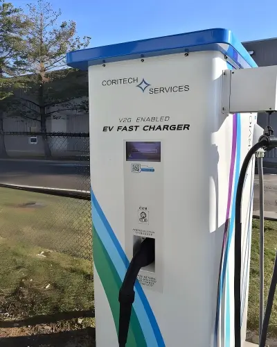
Figure 2. Ultra-fast charging depends on the complete power-delivery chain, not only the battery cell.
Test 2: How high does the temperature rise, and how large is the gradient?
High current increases ohmic and polarization heating, but the assumption that lower temperature is always safer is also misleading. Low temperature slows ion transport and lithium intercalation into graphite, increasing the risk of lithium plating. Excessive temperature, by contrast, accelerates side reactions and material degradation. Fast-charging tests should therefore measure more than a single case temperature. They should track the maximum temperature, temperature differences across locations, the rate of temperature rise, and thermal lag after charging stops.
Research has shown that short-term temperature modulation can improve fast-charging kinetics in energy-dense batteries. Under specific cell, electrolyte, and thermal-management conditions, Wang et al. charged a 265 Wh kg−1 battery to 70%–75% SOC in 11–12 minutes and reported 900 to 2,000 cycles [3]. The result shows that temperature can be incorporated into a fast-charging protocol, but it cannot be directly extrapolated to other chemistries, electrode loadings, or pack designs. Engineering validation must still be repeated across ambient temperatures, cooling capacities, and thermal boundary conditions.
Test 3: Has lithium plating begun at the anode?
Lithium plating is a central risk when fast charging graphite-based anodes. If lithium ions cannot intercalate into graphite quickly enough, metallic lithium may deposit on the anode surface. This can consume active lithium, accelerate capacity loss, and, under certain conditions, increase the risk of an internal short circuit. Low temperature, high SOC, high C-rate, and aging generally narrow the safe charging window [2,4]. A cell that does not immediately heat up or fail has not necessarily avoided lithium plating.
Lithium plating can be evaluated using a combination of post-charge voltage relaxation, coulombic efficiency, incremental-capacity or differential-voltage analysis, impedance, pressure, and thickness changes, followed by teardown validation when necessary. Huang et al. used the pressure change per unit of charge, dP/dQ, to identify the onset of lithium plating and demonstrated a proof-of-concept protocol that adjusted charging dynamically at 0 °C [4]. However, detection methods differ in their sensitivity to cell construction, clamping pressure, temperature gradients, and aging. A lithium-plating boundary should not rely on a single signal.
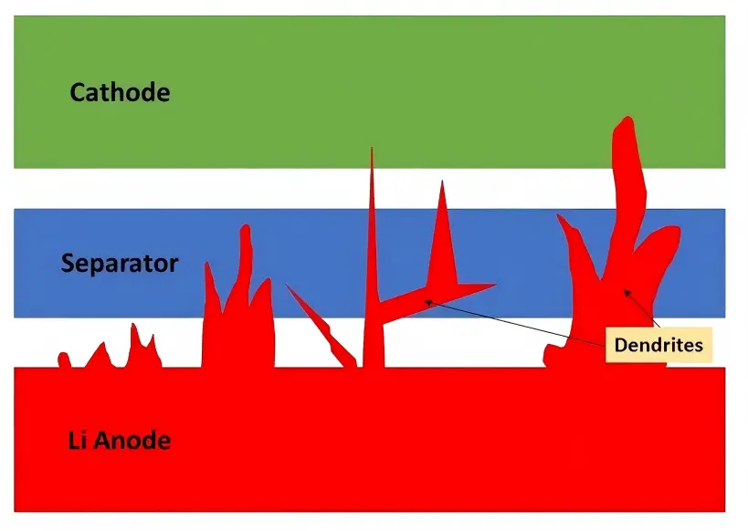
Figure 3. Lithium deposits can grow toward the separator and increase short-circuit risk.
Test 4: How do capacity and resistance change after fast charging?
One fast charge proves only that energy was delivered in that cycle. It does not prove that the battery will remain usable over time. Life testing should periodically include low-rate capacity checks, direct-current resistance or pulse-power measurements, and records of energy efficiency, constant-voltage duration, and self-discharge. Using cycle count as the only horizontal axis can also hide differences in energy throughput and time spent at high SOC between protocols.
Mathieu et al. compared the aging of three commercial lithium-ion cells across different charging currents, cutoff voltages, and ambient temperatures. They found that the effects of fast charging depended strongly on cell chemistry and internal design, and that the temperature associated with minimum aging differed among cells [5]. A fast-charging strategy validated for one cell at 25 °C cannot therefore be transferred directly to another cell. Nor can a small number of fresh samples represent batch variation and aged-cell behavior.
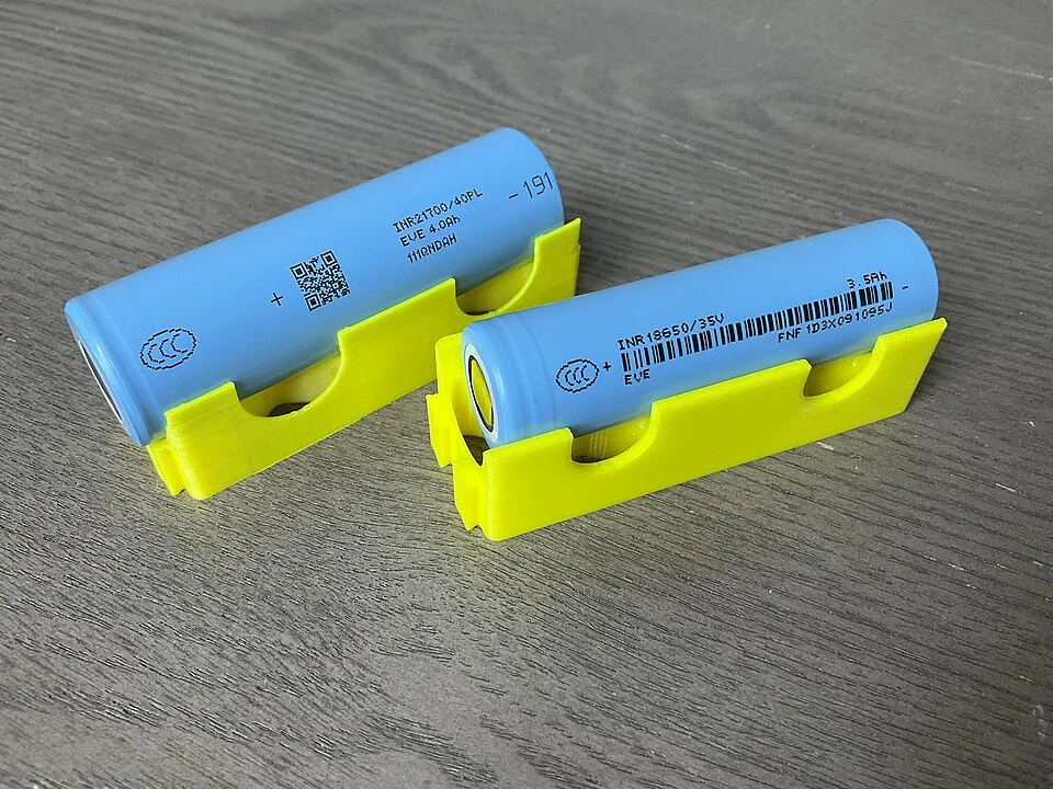
Figure 4. Cell size and internal design can differ even within the same broad battery family, so fast-charging results must be validated for each product.
Test 5: Does the protocol cover the SOC, temperature, and SOH matrix?
A practical ultra-fast-charging strategy is not a single current value. It is a control profile that changes with SOC, temperature, and state of health (SOH). Higher current may be permitted at low SOC, while current usually needs to taper near high SOC. The allowable current should also decrease at low temperature, when cooling is insufficient, or when aging raises internal resistance. A test matrix should cover initial and target SOC, ambient temperature, cooling conditions, sample variation, and multiple SOH levels, rather than presenting only the best result from a fresh cell at room temperature.
When a protocol contains multiple current steps, timing points, and cutoff conditions, the number of parameter combinations grows rapidly. Attia et al. combined early-life prediction with Bayesian optimization to screen 224 candidate ten-minute fast-charging protocols in a closed loop. Long-life candidates were identified in 16 days, whereas the study estimated that exhaustive testing without early prediction would have required more than 500 days [6]. Artificial intelligence can therefore reduce low-value experiments, but only when the test data are accurate, the constraints are explicit, and the final candidates undergo independent lifetime validation.
Test 6: What happens when sensing, cooling, or the BMS fails?
Ultra-fast charging moves the operating point closer to voltage, temperature, and power limits, so the system must be shown to exit safely under fault conditions. Representative scenarios include voltage or temperature sensor drift, reduced cooling capacity, contactor faults, communication loss, worsening cell imbalance, overcharge, and external short circuits. Evaluation should go beyond whether a fire occurs. It should include protection response time, maximum cell voltage, local temperature rise, venting behavior, and post-fault diagnosability.
IEC 62660-3:2022 specifies basic safety tests and acceptance criteria for lithium-ion cells and cell blocks used in electric road vehicles, covering intended use and reasonably foreseeable misuse or incidents [7]. Compliance is a baseline, not evidence that a particular 10C charging strategy has been validated across every combination of SOC, temperature, aging state, and system fault. Product-level test plans must define additional boundaries based on cell chemistry, construction, BMS logic, and vehicle thermal management.
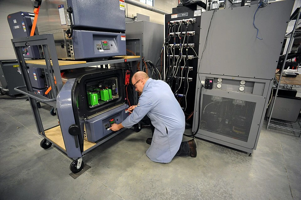
Figure 5. Controlled laboratory testing helps engineers evaluate overheating risk and verify battery protection under abnormal conditions.
How to judge a five-minute charging test report
When reviewing a test report, look first for the following information:
The SOC window represented by the charging time, together with the peak and average C-rates.
Ambient temperature, initial cell temperature, cooling method, and maximum temperature difference.
Cell chemistry, capacity, energy density, sample size, and sample consistency.
The lithium-plating criterion and whether it was cross-checked using a second method or teardown analysis.
The cycle-life endpoint and the changes in capacity, internal resistance, and energy efficiency.
Whether the fast-charging strategy automatically derates or exits under low temperature, high SOC, aging, and fault conditions.
If a report shows only one room-temperature charging curve without specifying the SOC window, temperature rise, lithium plating, or post-cycling condition, it demonstrates only that the equipment delivered high power once. It does not establish production-ready ultra-fast-charging capability.
Frequently asked questions
Does 10C always damage a battery?
Not necessarily. Electrode design, energy density, electrolyte, temperature, SOC window, charging protocol, and cooling conditions also affect the outcome. Higher C-rates generally leave less margin for ion transport and thermal management, so lithium-plating, lifetime, and safety tests are required to establish the operating boundary.
Is fast charging safer after warming the battery?
Moderate warming can improve reaction kinetics and reduce low-temperature lithium-plating risk, but high temperature also accelerates side reactions. Temperature modulation must be validated together with cell materials, heating duration, cooling capacity, and safety limits. Hotter is not automatically better.
Can AI replace long-term fast-charging tests?
No. AI can help screen protocols, predict early trends, and select the next experiments, but the model depends on high-quality data and must be validated using samples that were not part of training. Physical testing remains indispensable for final lifetime and safety boundaries.
Conclusion: Ultra-fast charging is ultimately a validation challenge
10C fast charging is not an isolated C-rate specification. It is a system capability jointly determined by cell design, thermal management, charging protocol, the BMS, and test equipment. A meaningful validation must answer three questions: Was energy delivered at the target rate? Did degradation remain acceptable? Could the system exit promptly under adverse or fault conditions? Only when the evidence covers high-current response, thermal behavior, lithium plating, lifetime, the protocol matrix, and fault safety can a five-minute charge progress from a demonstration to a reproducible and verifiable engineering capability.
References
[1] International Energy Agency (IEA). Ultra-fast charging batteries. Global EV Outlook 2026 (2026). https://www.iea.org/reports/ultra-fast-charging-batteries
[2] Tomaszewska, A. et al. Lithium-ion battery fast charging: A review. eTransportation 1, 100011 (2019). https://doi.org/10.1016/j.etran.2019.100011
[3] Wang, C.-Y. et al. Fast charging of energy-dense lithium-ion batteries. Nature 611, 485–490 (2022). https://doi.org/10.1038/s41586-022-05281-0
[4] Huang, W. et al. Onboard early detection and mitigation of lithium plating in fast-charging batteries. Nature Communications 13, 7091 (2022). https://doi.org/10.1038/s41467-022-33486-4
[5] Mathieu, R., Briat, O., Gyan, P. & Vinassa, J.-M. Comparison of the impact of fast charging on the cycle life of three lithium-ion cells under several parameters of charge protocol and temperatures. Applied Energy 283, 116344 (2021). https://doi.org/10.1016/j.apenergy.2020.116344
[6] Attia, P. M. et al. Closed-loop optimization of fast-charging protocols for batteries with machine learning. Nature 578, 397–402 (2020). https://doi.org/10.1038/s41586-020-1994-5
[7] International Electrotechnical Commission. IEC 62660-3:2022: Secondary lithium-ion cells for the propulsion of electric road vehicles—Part 3: Safety requirements (2022). https://webstore.iec.ch/en/publication/65084