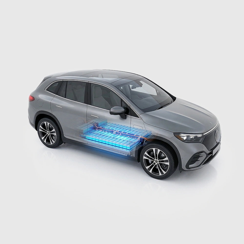
The hidden error begins when two systems run independently
A standalone temperature chamber and a standalone battery cycler each have their own controller, clock, program state, and data file. When the chamber reports that it has reached the target temperature, the cycler does not know whether the sample has actually equilibrated. Once cycling begins, the chamber may not know the current, test step, or heat-generation level. Both devices can appear to operate normally while the combined system still has an unanswered question: who decides that the conditions are satisfied, who triggers the next step, and which device stops first when an abnormal condition occurs?
Manual operation usually fills this gap. A few short tests can be supervised, but as channel count, temperature points, and cycle duration increase, soak time, start order, channel identification, and file naming begin to drift. What looks like a difference between samples may actually be a difference in workflow created by two devices that do not share state information.
Temperature and electrical steps need shared trigger conditions
A reliable start condition is not simply 'press start when the chamber reaches temperature.' Test initiation should require several conditions to be true at the same time:
Test start = temperature ready + soak complete + channel ready + safety state normal
'Temperature ready' must specify whether it refers to chamber air or a representative cell. 'Soak complete' requires an allowed deviation, a rate-of-change limit, and a hold time. 'Channel ready' confirms range, wiring, and sample mapping. 'Safety state normal' covers critical conditions such as the door, fan, overtemperature protection, and short-circuit protection. Only when these conditions belong to one workflow are the thermal program and the electrical program truly connected.
At the system level, a more reliable design lets environmental control and electrical testing follow the same test recipe or state machine, reducing the manual handoff from 'chamber complete' to 'operator confirmation' to 'cycler start.' Integrated control is one implementation, but a shared trigger does not remove sample thermal inertia. If actual cell temperature matters, a representative sample still needs temperature measurement to establish the ready criterion.
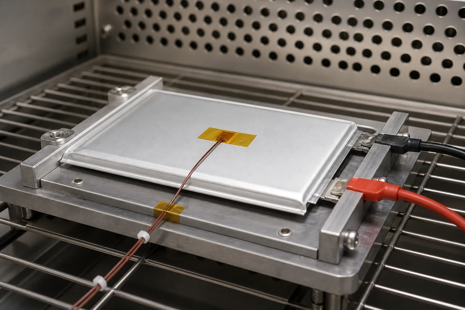
Figure 2. A surface thermocouple records the temperature of a representative cell. Chamber air can reach the setpoint before the cell itself reaches thermal equilibrium.
Low-temperature capacity tests expose timing errors
At low temperature, ion transport and interfacial reactions slow, polarization increases, and the cell reaches the cutoff voltage more easily. If testing starts as soon as the chamber air reaches its target while the cell interior is still changing temperature, the first capacity segment, direct-current internal resistance, and voltage plateau contain both thermal transition and electrochemical response. Waldmann et al. observed different dominant aging mechanisms when commercial cells were cycled from -20 °C to 70 °C, showing that temperature is not a background variable that can be corrected by simple post-processing [2].
Charge and discharge also change cell temperature. The classical energy balance shows that current, the difference between terminal voltage and open-circuit voltage, and reversible entropic heat jointly determine the instantaneous heat source [1]. Troxler et al. further showed that a cell with a temperature gradient can exhibit different impedance from an isothermal cell at the same theoretical average temperature [3]. A synchronized workflow should therefore log three separate events: the chamber reaches the control band, the sample is permitted to start, and the electrical step begins. A single label such as '25 °C test' is not enough.
Multi-temperature comparisons are vulnerable to sequence and mapping errors
When one chamber is used sequentially for several temperatures, temperature effects become entangled with test order, batch differences, and cell aging. If the sequence is 25 °C, then 0 °C, then 45 °C, the last two results differ not only in temperature but also in sample history and test date. If channels and files are manually reassigned at each transition, the relationship among temperature zone, sample, and data becomes even more fragile.
Independent temperature zones can compare several temperatures within the same time window and reduce sequence effects. A fixed channel-zone-sample mapping gives each data record a defined origin from the moment the task is created. The engineering question is not whether more zones are always better. It is how many temperatures must run in parallel, how many channels each zone needs, and whether cross-temperature comparisons require the same batch and the same time baseline.
Temperature transitions must be traceable test events
A common error in high-low-temperature programs is to start the next charge-discharge step immediately after the controller reports the target temperature. The air sensor usually responds first, while the cell continues heating or cooling because of its thermal mass. Cell size, position, and fixture design introduce additional thermal lag. If transition time exists only in the chamber file and has no matching event in the electrical data, later analysis cannot easily determine whether a voltage or resistance change came from a thermal transition or a material response.
A more robust method records 'environment enters control band,' 'representative sample becomes stable,' and 'electrical step is released to start' as separate entries in one event log. Stability can combine |Tcell - Ttarget|, |dTcell/dt|, and a hold time, with project-specific thresholds established through repeatability testing. This preserves the chamber-control record while tying each segment of electrical data to the corresponding thermal state.
Four overlooked handoff points in split systems
The first handoff is from temperature ready to electrical start, where operator response changes the effective soak time. The second is the mapping among temperature zone, position, sample, and channel; rewiring or moving samples can create identification errors. The third is the pair of clocks and data files, which are vulnerable to clock drift and missing events during post-processing. The fourth is abnormal-state recovery: after a power interruption, overtemperature event, or fan fault, the two devices may stop in different steps.
These problems do not always appear as obvious failures. More often, the test finishes but repeatability deteriorates and abnormal batches become difficult to trace. Each sample should have a unique identifier, the zone-position-channel mapping should be fixed, clocks and step numbers should be shared, and stop, recovery, and retest rules should be defined. When environmental and channel control share task information, these relationships can be bound when the test is created instead of reconstructed manually during data analysis.
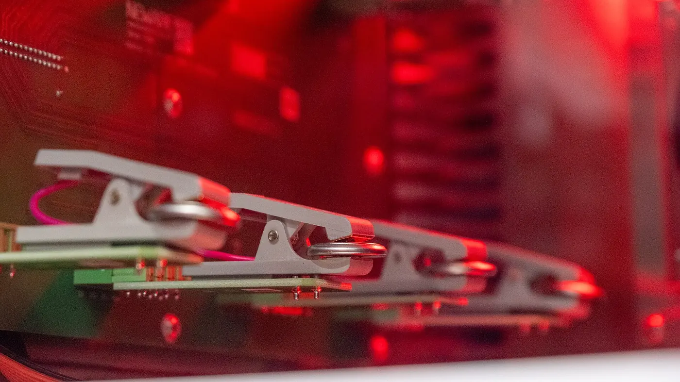
Figure 3. Multiple coin cells are secured in a test fixture. As channel count increases, sample identifiers, fixture positions, and test channels should be bound when the task is created.
Safety protection must respond with the test state
When the chamber and cycler are independent, an overtemperature event, fan fault, open door, or power interruption may be detected by only one device. Environmental control may stop while the test channel continues at the original current. Alternatively, the cycler may resume its step before the chamber temperature has recovered. In a long unattended test, this inconsistent state can be harder to detect than a clear shutdown.
A complete safety logic defines which environmental abnormalities must pause current, which faults allow breakpoint recovery, which temperature conditions must be satisfied again before restart, and how fault and recovery timestamps are retained. If an environmental alarm can directly change the electrical channel state, the interlock becomes clearer. Protection coverage must still be confirmed for the specific model and project risk; the ability to link devices does not mean that every safety condition is automatically covered.
A reproducible temperature-control and cycling workflow
Step 1: establish a unique sample-zone-position-channel mapping and write it into the test task.
Step 2: define the temperature-ready condition. Specify the roles of the setpoint Tset, the chamber verification point Tair, and the representative sample temperature Tcell, and record sensor position, attachment method, and sampling interval.
Step 3: validate the temperature field and maximum heat-generation condition under the actual load. An empty-chamber temperature result does not prove that Tcell remains compliant during cycling. Record temperature rise at the highest current, longest pulse, or worst-cooled position.
Step 4: use temperature ready, soak complete, channel ready, and safety state as joint release conditions for the electrical program instead of relying on operator judgment.
Step 5: give thermal and electrical data a shared clock, step number, and event markers. Temperature transitions, rest, charge, discharge, alarms, and recovery should all be locatable on the same timeline.
Step 6: define the post-fault state machine: whether current is interrupted immediately, whether continuation is allowed, whether temperature must stabilize again before restart, and which data must be marked invalid.
Step 7: export complete metadata. The result file should include actual temperature, temperature fluctuation, spatial measurement points, heating and cooling time, stability-wait logic, maximum sample temperature, channel mapping, and abnormal-event records. Standards such as IEC 62660-1 emphasize obtaining capacity, power, energy, and life data under specified procedures and conditions. A laboratory following a standard method should also document its own synchronization and temperature-control implementation [4].
Choose the setup by its synchronization task
Long-term cycling near room temperature prioritizes stability, channel density, and unattended operation. Formula comparisons across several temperatures prioritize independent zones and parallel channels. Low-temperature rate tests, temperature cycling, and extreme-environment validation require a defined temperature range, heating and cooling capability, and step-trigger logic. Before selecting equipment, define the sample count, target current, number of simultaneous temperature points, transition sequence, and whether thermal state must automatically trigger charge-discharge steps.
Equipment specifications must be separated from system results. Temperature fluctuation, deviation, sampling time, and electrical accuracy describe equipment capability. Actual cell temperature, thermal lag, self-heating, and the loaded temperature field must be validated under project conditions. A suitable integrated system can reduce handoffs and improve data correspondence, but it does not replace sensor placement, loaded validation, or judgment about method boundaries.
When an integrated system is the better fit
If the test frequently changes temperature, must run unattended for long periods, or is vulnerable to manual errors in sample-zone-channel mapping, combining environmental and charge-discharge control in one system becomes more useful. The NEWARE All-in-One Battery Testing System manages temperature and charge-discharge testing through the host software, making thermal events, electrical steps, and channel data easier to align on one timeline. It addresses workflow coordination; it does not replace temperature-field validation [5].
For example, the official page for the WGDW-20L-20C-220V-2U High-Low Temperature Mini All-in-One Testing System lists 16 test channels, a temperature range of -20 °C to 85 °C, current and voltage accuracy of ±0.02% F.S., a sampling interval of 100 ms, temperature fluctuation of no more than ±0.5 °C, and temperature deviation of ±2 °C [6]. These specifications can support initial screening, but formal testing should still validate the loaded temperature field, representative cell temperature, and maximum heat-generation condition.
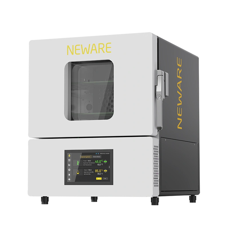
Figure 4. NEWARE WGDW-20L-20C-220V-2U High-Low Temperature Mini All-in-One Testing System. The product image supports the equipment-selection discussion at the end of the article.
Key takeaways
The most hidden error in battery temperature testing is not only the difference between set temperature and cell temperature. It is the absence of shared start conditions, channel mapping, event logs, and abnormal-state logic between the temperature program and the charge-discharge program. Two devices operating normally on their own do not guarantee a reproducible combined test.
If the main risks are frequent temperature transitions, long unattended operation, channel mapping, or abnormal recovery, an integrated system can reduce manual handoffs and post-processing. If the test requires more sample space, higher current, special fixtures, or a third-party environmental system, a split setup may remain more flexible. The decisive question is not the label 'integrated' or 'split,' but whether the system implements a shared clock, joint triggers, fixed mapping, and traceable abnormal-state logic.
References
[1] Bernardi, D.; Pawlikowski, E.; Newman, J. A General Energy Balance for Battery Systems. Journal of The Electrochemical Society 132, 5-12 (1985). https://doi.org/10.1149/1.2113792
[2] Waldmann, T.; Wilka, M.; Kasper, M.; Fleischhammer, M.; Wohlfahrt-Mehrens, M. Temperature dependent ageing mechanisms in Lithium-ion batteries - A Post-Mortem study. Journal of Power Sources 262, 129-135 (2014). https://doi.org/10.1016/j.jpowsour.2014.03.112
[3] Troxler, Y.; Wu, B.; Marinescu, M.; Yufit, V.; Patel, Y.; Marquis, A. J.; Brandon, N. P.; Offer, G. J. The effect of thermal gradients on the performance of lithium-ion batteries. Journal of Power Sources 247, 1018-1025 (2014). https://doi.org/10.1016/j.jpowsour.2013.06.084
[4] IEC 62660-1:2018. Secondary lithium-ion cells for the propulsion of electric road vehicles - Part 1: Performance testing. International Electrotechnical Commission (2018).
[5] NEWARE. All-in-One Battery Testing System. https://www.neware.net/products/all-in-one-testing-system.html (accessed 3 August 2026).
[6] NEWARE. WGDW-20L-20C-220V-2U High-Low Temperature Mini All-in-One Testing System. https://www.neware.net/products/all-in-one-testing-system/wgdw-20l-20c-220v-2u/22.html (accessed 3 August 2026).