A stable current is not automatically true self-discharge
A potentiostatic method uses a stable voltage source to match the cell's open-circuit voltage and measures the current required to hold the terminal voltage constant. After the system approaches equilibrium, the external compensation current is used to represent cell self-discharge. Compared with tracking open-circuit-voltage changes over a long rest period, this method provides a more direct current signal, but it transfers the measurement challenge to microcurrent metrology, loop stabilization, temperature control, and connection quality. [1,2,5]
In one study of 21 commercial 4.7 Ah cylindrical cells, the current measured near 30% state of charge (SOC) and 23 °C was approximately 3-6 µA, compared with an actual self-discharge level of about 0.25 µA. The current increased as cell temperature rose toward 40 °C. These results show both that microamp-level signals can be measured directly and that temperature, SOC, and individual-cell relationships limit the portability of any single numerical threshold. [1] These values describe the scale observed under the reported test conditions; they should not be used as universal acceptance limits for other products.
Turn the measured value into a verifiable budget
For detailed equipment analysis, the useful statement is not simply that the measured current equals self-discharge. Instead, write the reading as a sum of independent contributions:
I_meas = I_cell + I_fixture/environment + I_instrument + I_transient/environment
Here, I_cell is the internal loss signal of interest; I_fixture/environment includes unintended paths formed by insulation and surface contamination; I_instrument includes input offset, range drift, and residual source current; and I_transient/environment includes voltage mismatch before connection, electrochemical relaxation, temperature changes, and transients caused by cable motion. These terms can have the same or opposite signs, so a value close to zero does not prove that the system is error-free. The cell arrangement in Figure 1 also shows why lead-resistance calibration changes the time needed to reach steady state and why the transient response must be separated from the assessment of steady-state current. [1]
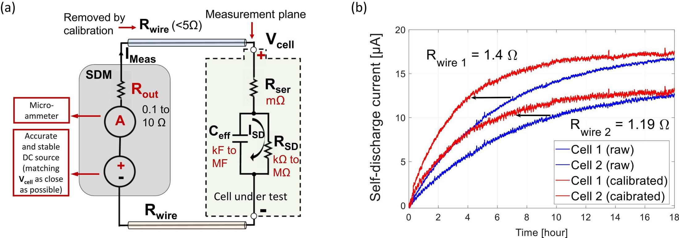
Figure 1. Equivalent circuit for potentiostatic self-discharge measurement and the current response before and after lead-resistance calibration
How equipment errors enter the current reading
Channel offset and drift can create location-dependent anomalies
If one channel consistently reads high after startup or under an equivalent input, while the deviation disappears when the cell is moved, first suspect that channel's zero point, analog front end, or calibration state. Offset that repeats over only a short period may still drift over longer durations or as temperature changes. The equipment warm-up and response test should therefore measure not only the baseline, but also its extreme range and slope over time.
Insulation leakage can make a fixture look like a self-discharging cell
The enclosure, cables, connectors, and fixture insulation all present finite resistance. When a test voltage is applied across these unintended paths, leakage current is added directly to the measured low-current signal. Humidity, contamination, and improper insulation materials reduce insulation resistance; electrostatic charge stored in insulating materials, cables, and fixture components can also affect the result over time. [3] Fixture cleanliness is therefore not merely a maintenance item; it is part of the measurement model.
Temperature changes both the cell and the measurement system
Temperature can simultaneously change the cell's open-circuit voltage (OCV), self-discharge reaction rate, instrument offset, and insulation condition. In a potentiostatic measurement, even if the cell itself is not abnormal, temperature-driven OCV movement can force the external source to supply or absorb current. Figure 2 shows the OCV response to temperature steps and the dependence of the voltage temperature coefficient on SOC. The experiment illustrates that current caused by a temperature disturbance can resemble a change in SOC. To compare a potentiostatic result with an OCV-based result, the SOC reference and rest history must be aligned and temperature effects minimized. [1,2,4] Record the actual cell temperature rather than relying only on the chamber setpoint.
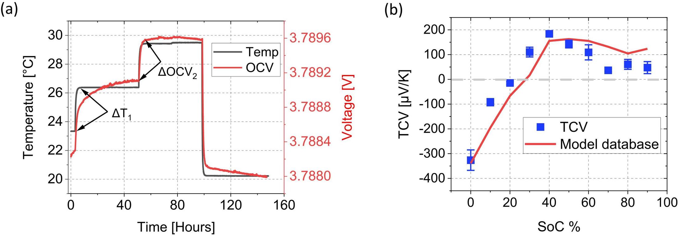
Figure 2. Open-circuit-voltage response to temperature steps and variation of the voltage temperature coefficient with SOC
Connection transients and cable motion can create false peaks
When the source voltage differs slightly from the cell OCV at connection, a transient charging or discharging compensation current appears. Cells that have just been charged or discharged also undergo concentration relaxation and interfacial relaxation. In high-impedance systems, cable bending, friction, or vibration may generate transient currents through triboelectric or piezoelectric effects. [3] These errors often appear as peaks followed by decay and do not necessarily share the same time constant as cell self-discharge. A reading taken at one arbitrary point at the end of a fixed process should not be used alone for judgment.
A four-part validation chain separates equipment anomalies from cell anomalies
Validation 1: Open-circuit baseline
With no cell connected, measure the zero-current behavior using the same range, cable, fixture, and environmental chamber configuration as the actual test. Record the zero point, peak-to-peak noise, steady-state slope, and response to temperature and humidity changes for every channel. State clearly whether the baseline configuration uses an open circuit, a short circuit, or a dedicated dummy termination because each configuration has a different physical meaning. Set acceptance criteria jointly from the target signal magnitude and the equipment error budget, rather than copying the expected microamp value of the sample.
Validation 2: Simulated load
Use a verified high-value standard resistor or a traceable leakage-current simulator to produce current under voltage conditions similar to the cell test. Use Ohm's law, I = V/R, to compare the stable setpoint with the measured value, acquisition curve, linearity, range switching, stabilization time, and channel-to-channel variation. The nominal resistor value, voltage coefficient, temperature coefficient, and connection method must suit the target current range. The simulated load also requires clean, dry connections and sufficient stabilization time.
Validation 3: Swap test
When one cell appears abnormal, exchange it with a normal cell between channels and, when necessary, also exchange the fixture or cable. If the high reading follows the cell, evidence for a cell anomaly becomes stronger. If it remains with the original channel or fixture, investigate the equipment path first. If the anomaly disappears, contact resistance, contamination, or insufficient stabilization may have been involved. Change only one factor in each swap while keeping SOC, temperature, rest time, and the test procedure unchanged.
Validation 4: Independent reference method
For critical lots or samples, use a stable reference cell to extend the observation period, track OCV stabilization, or perform a capacity check. The independent method does not need a simple one-to-one numerical conversion with the potentiostatic result, but it should agree on the repeatability, direction, and subsequent failure verification of the anomaly. If the two methods disagree, first examine temperature, rest history, SOC, capacity effect, and the influence of OCV slope before assigning a cell mechanism. [2,4]
Locate an anomaly by observing what moves with it
During troubleshooting, ask what the anomaly follows rather than only why the number is high. The following migration patterns are especially useful:
Anomaly follows the cell: prioritize a true cell difference, then confirm that temperature, SOC, and rest history are consistent before conducting an independent retest.
Anomaly remains with the channel: prioritize the channel zero point, range, calibration, grounding, and analog front-end condition.
Anomaly follows the fixture or cable: prioritize insulation, contamination, connector sealing, mechanical stress, and improper materials.
Anomaly appears only in a certain period or environment: prioritize chamber fluctuation, equipment warm-up, grounding, power-frequency interference, airflow cycles, and nearby operations.
This migration logic strengthens the chain of evidence, but it does not justify inferring an internal short circuit directly from a current-trace shape. Similar high-current readings, drift, or peaks can arise from different causes. When needed, combine temperature, OCV, channel logs, capacity tracking, and failure analysis.
A multichannel system needs an equipment-control routine
Checks before every lot
Confirm that the equipment has reached the specified warm-up state, the chamber is stable, and the test program and firmware versions are correct. Run an open-circuit baseline or reference channel, confirm that the fixture surface is clean and dry, and verify that cables have not been rearranged without assessment. For products prone to connection shock, disconnect the cell before changing the programmed output and allow the equipment to settle.
Periodic metrology verification
Schedule simulated-load tests, channel rotation with a reference cell, range cross-checks, and insulation checks according to risk and use frequency. A control chart is suitable for detecting slow drift, while a one-time calibration certificate proves only the condition at the calibration date. After replacing a fixture, cable, channel board, or chamber position, reconfirm the baseline and channel consistency.
Close the loop on abnormal events
Retain raw traces, cell identifiers, channel numbers, fixtures, temperature, humidity, software version, equipment status, and test timestamps so the anomaly can be reproduced. After maintenance or cleaning, do not confirm recovery with only a blank test. Reuse the original abnormal sample or an equivalent load to verify that the deviation has disappeared.
A directly reusable equipment validation workflow
1. Define the measurement task: specify chemistry, SOC, nominal voltage, target current range, temperature range, allowable uncertainty, and decision risk.
2. Verify the open-circuit baseline: record each channel's offset, noise, drift, and environmental response under the actual range and fixture arrangement.
3. Verify the simulated load: cover low, middle, and high points in the target range and assess accuracy, repeatability, linearity, and stabilization time.
4. Verify channel consistency: rotate the same standard load and reference cell across channels to determine whether location effects are below the project error limit.
5. Verify with real samples: select normal, borderline, and abnormal cells and examine repeatability, migration behavior, and agreement with extended OCV rest or another independent method.
6. Freeze the test version: document the program, warm-up, temperature and humidity, fixture, cleaning, steady-state basis, and anomaly-retest rules.
7. Establish long-term monitoring: use the open-circuit baseline, reference load, and reference cell to trend drift, and trigger reconfirmation after equipment repair or environmental change.
The role of the test platform in a validation project
A self-discharge test platform must execute potentiostatic control reliably, record complete microcurrent traces, and associate channel, temperature, software version, abnormal events, and cell identification. Multichannel capacity becomes useful only after channel consistency has been verified. If some channels have different baselines or response times, additional channels increase uncertainty rather than sample throughput.
When self-discharge test equipment is treated as a platform integrating potentiostatic control, microcurrent metrology, and multichannel data management, project acceptance should use the target cell and an equivalent load together. Key checks include voltage-matching stability, the baseline and noise of the target range, channel consistency, coordination with temperature control, fixture insulation, raw-data integrity, and anomaly traceability. The equipment provides the measurement foundation, while decision limits must be established jointly from product characteristics, the measurement uncertainty budget, and the screening risk.
Recommended equipment for this validation workflow
For projects that need direct potentiostatic self-discharge measurement with temperature control, we recommend the NEWARE CT-9008-SD-5V300mA Self-Discharge Tester. Its architecture matches the validation logic discussed above: it measures compensation current under constant-voltage control and integrates the test host with a constant-temperature system, reducing the interface and synchronization risks associated with a separate chamber. According to the current official product page, the system provides a 0-300 mA current range with a 0.1 µA minimum interval, ±0.02% of full-scale current accuracy, a -5 V to +5 V voltage range, and ±0.01% of full-scale voltage stability. Project acceptance limits should still be verified against the ordered configuration, target cell, fixture, and uncertainty budget.
The equipment should be commissioned with the same four-part chain used for any microcurrent system: establish the open-circuit baseline, verify gain with a simulated load, rotate a reference cell across channels, and confirm abnormal samples by controlled swaps. Integrated temperature control reduces one major error source, but it does not replace checks for channel offset, fixture leakage, connection transients, or long-term drift.
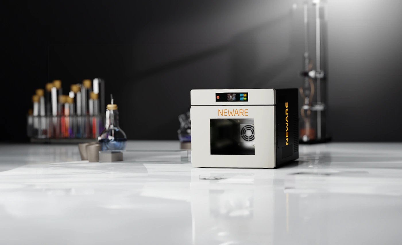
Figure 3. NEWARE CT-9008-SD-5V300mA Self-Discharge Tester recommended for potentiostatic microcurrent measurement with integrated temperature control
Five common validation mistakes
Relying on only one zero-point calibration. A single calibration cannot cover baseline drift caused by changes in temperature, time, range, and connection state; in-process baseline monitoring is still required.
Confusing repeatability with accuracy. The same bias can be reproduced very consistently. A stable, repeatable result is not necessarily a correct result.
Repeating an anomaly only on the original channel. Repeating the same error path cannot distinguish a cell anomaly from a channel anomaly; the test design should cross the channel, cell, and fixture.
Averaging transients away. Averaging can make a trace look smoother but can also conceal leakage, drift, or temperature compensation current. Raw data must be retained.
Using equipment failure as a reason to relax screening limits. Relaxing the limit reduces the ability to identify genuinely abnormal cells. Restore the measurement system first.
Conclusion
A trustworthy self-discharge test does not begin with a smooth curve. It begins with a verifiable measurement loop. Use an open-circuit baseline to determine what the equipment generates by itself, a simulated load to verify gain and response, channel-cell swaps to observe what an anomaly follows, and a reference cell to complete long-term review. Only when the source of current is controlled and traceable can a microamp reading support an engineering decision.
References
[1] Al-Zubaidi R-Smith, N., Moertelmaier, M., Gramse, G., Kasper, M., Ragulskis, M., Groebmeyer, A., Jurjovec, M., Brorein, E., Zollo, B., Kienberger, F. Fast method for calibrated self-discharge measurement of lithium-ion batteries including temperature effects and comparison to modelling. Energy Reports, 2023, 10: 3394-3401. https://doi.org/10.1016/j.egyr.2023.10.031
[2] Brorein, E. Self-discharge measurements: How external factors impact results. Keysight Technologies, 2021. https://www.keysight.com/blogs/en/tech/bench/2021/01/08/achieving-valid-self-discharge-measurements-how-external-factors-impact-results
[3] Tektronix. Keithley Low Level Measurements Handbook, 7th Edition. Sections 2.3 and 2.6. https://www.tek.com/en/documents/product-article/keithley-low-level-measurements-handbook---7th-edition
[4] Brorein, E. Shortening Lithium Ion Cell Manufacturing Time: A Comparative Study of Two Methods of Making Self-Discharge Measurements. Keysight Technologies, 2020. https://www.keysight.com/blogs/en/tech/bench/2020/06/03/shortening-lithium-ion-cell-manufacturing-time-a-comparative-study-of-two-methods-of-making-self-discharge-measurements
[5] Keysight Technologies. Evaluate Self-Discharge of Lithium-Ion Cells in a Fraction of the Time Traditionally Required. Application Note 5992-2517. https://www.keysight.com/fr/en/assets/7018-05892/application-notes/5992-2517.pd