Introduction: key technical challenges in Li-S battery commercialization
As a prime representative of next-generation high-energy-density energy storage systems, Lithium-Sulfur (Li-S) and lithium-metal batteries have become the focal point of global research and development due to their exceptionally high theoretical energy densities. However, in industrial development, the shuttle effect remains the primary technical bottleneck limiting their long cycle life.
What is the shuttle effect?
During charge and discharge cycles, the solid-state elemental sulfur at the cathode transforms into a series of long-chain lithium polysulfides (Li2Sn, 4≤n≤8). These intermediate products dissolve readily into ether-based organic electrolytes and diffuse toward the lithium-metal anode under the drive of concentration gradients, where they undergo direct chemical side reactions with the highly reactive metallic lithium. These reactions reduce the long-chain intermediates into short-chain polysulfides or insoluble solid precipitates like Li2S2/Li2S, which then diffuse back to the cathode. This continuous parasitic cyclic reaction leads to active material loss, severe self-discharge, and a drastic degradation of Coulombic efficiency.
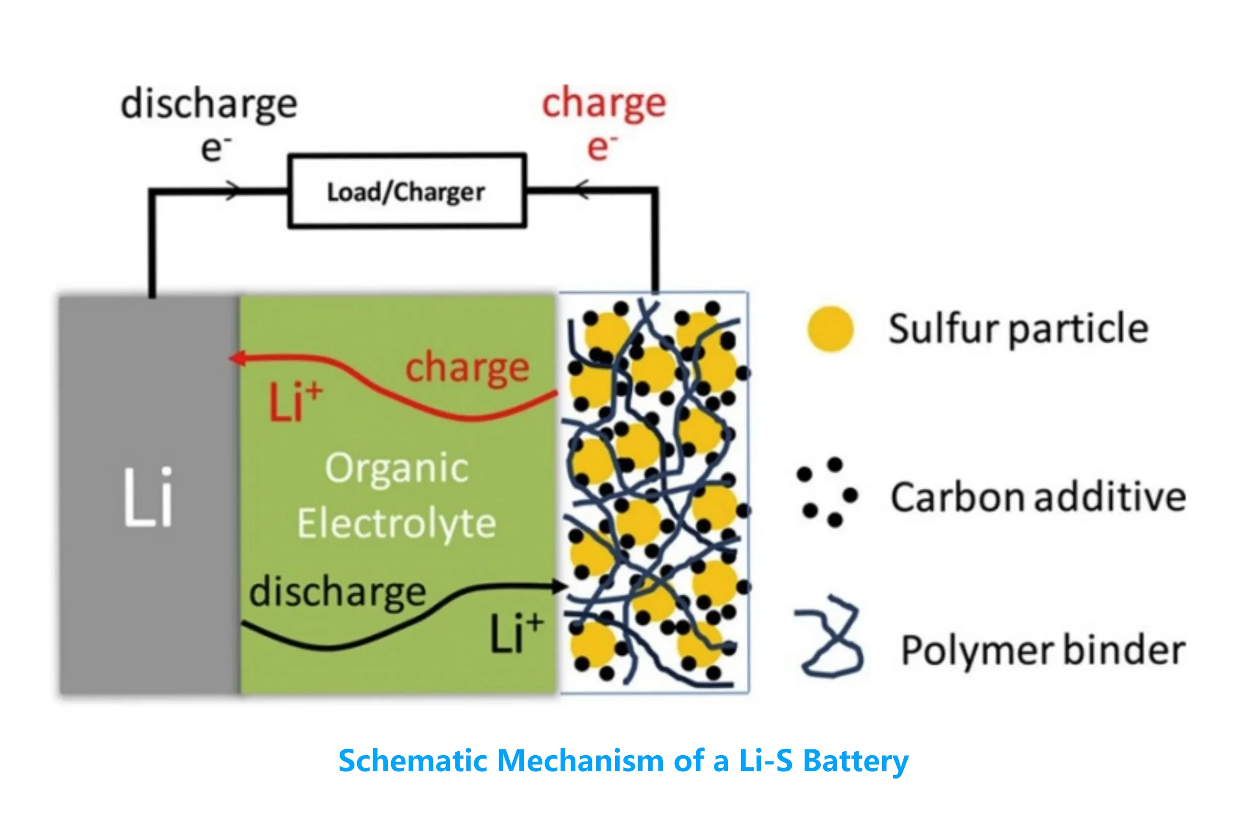 Figure 1: Schematic mechanism of electrochemical processes and material components in a Lithium-Sulfur (Li-S) battery structure.
Limitations of Ex-Situ characterization & the necessity of In-Situ EIS technology
To evaluate the shuttle effect, traditional destructive ex-situ characterizations require dismantling the battery at specific States of Charge (SOC). This approach is not only operationally tedious but also disrupts the authentic electrochemical equilibrium and transient interface structures inside the cell, leading to distorted test data.
In-situ Electrochemical Impedance Spectroscopy (In-situ EIS) technology provides a non-destructive alternative. By applying minor AC signal perturbations, in-situ EIS captures the resistance parameters of various internal kinetic steps in real time without interrupting the charge-discharge protocols and without the need to reposition the battery.
Since the internal states of a battery change dynamically over time during cycling, traditional slow frequency scanning induces severe time-distortion artifacts in the data. Consequently, to precisely capture the transient shuttle behaviors and dynamic evolutions of polysulfides, in-situ testing systems with high-frequency rapid scanning capabilities have become an absolute necessity for frontier battery research.
Kinetic mechanism of capturing the shuttle effect via high-frequency EIS
In the Nyquist plots generated by electrochemical impedance spectroscopy, different frequency ranges correspond to distinct physical and electrochemical processes. When the shuttle effect occurs, variations in electrolyte conductivity, the degradation and repair of the solid electrolyte interphase (SEI) film on the anode, and the charge transfer rates at the cathode are reflected in the impedance spectra in real time:
| EIS Feature | Frequency Range | Electrochemical Process | Dynamic Changes During Shuttle Effect |
Rb (Bulk Resistance) | High Frequency (High Freq) | Electrolyte conductivity, separator porosity, and contact resistance. | As discharge deepens, the massive dissolution of long-chain polysulfides increases electrolyte viscosity, causing the high-frequency intercept Rb to exhibit regular, periodic stepwise increments. |
Rsei (SEI Film Resistance) | Medium-High Frequency (Med-High Freq) | Passivation layer of the SEI film on the lithium-metal anode surface. | Dissolved polysulfides shuttle to the anode and react with metallic lithium, damaging the pristine SEI layer. The continuous degradation and repair mechanism of the SEI film during cycling dynamically expands the mid-to-high-frequency semicircle diameter. |
Rct (Charge Transfer Resistance) | Medium-Low Frequency (Med-Low Freq) | Electrochemical redox reaction rate at the cathode interface. | In the later stage of discharge, insoluble and insulating Li2S2/Li2S passivates the cathode surface, impeding electron and ion transport, which triggers an exponential expansion of the medium-to-low-frequency semicircle. |
Through high-frequency rapid in-situ scanning, R&D engineers can precisely capture impedance snapshots at specific voltage plateaus. Any anomalous fluctuations in the medium-to-high frequency impedance within characteristic voltage windows can quantify the peak intensity of polysulfide shuttling and parasitic side reactions during that specific stage.
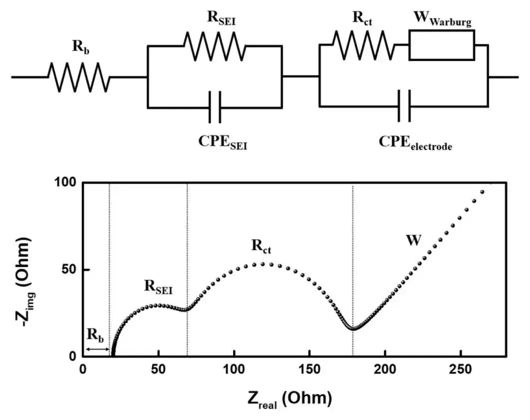
Figure 2. Typical Nyquist plot and its corresponding equivalent circuit model, illustrating the distribution of Rb, RSEI, Rct, and Warburg impedance (W ).
From mechanism to measurement: technical bottlenecks of In-Situ capturing
Although the aforementioned kinetic mechanisms are clearly defined in theory, the impedance fluctuations caused by polysulfide dissolution are extremely weak in practical testing, and the transient evolutions of interfacial reactions occur within seconds. Conventional charge-discharge testers or traditional workstations utilizing external matrix switchers are highly susceptible to high-frequency parasitic interference, response propagation delays, and measurement accuracy limitations. These bottlenecks easily submerge critical "impedance fingerprints" into background noise, resulting in severe distortion of dynamic test data. Therefore, the key to successfully translating theoretical methodologies into practice relies strictly on whether the underlying testing hardware satisfies the rigorous specifications of extreme in-situ environments.
Critical hardware specifications for High-Precision test equipment
Utilizing multi-channel electrochemical impedance spectroscopy to capture weak shuttle effect signals imposes stringent technical demands on the underlying battery testing equipment:
Independent EIS Generator per Channel: Traditional matrix switchers introduce significant parasitic capacitance and inductance interference, leading to high-frequency impedance data distortion. The system must achieve channel-level hardware integration, equipping each testing channel with a completely independent AC excitation source to guarantee the absolute authenticity of impedance data.
Wide Frequency Range & Rapid Scanning: The equipment must possess the capability to swiftly transition from several kHz down to the millihertz (mHz) low-frequency range. Both the current rise time and charge-discharge transition time must be ≤ 20 μs, enabling the system to intervene rapidly at transient inflection points of the battery's voltage curve and complete core frequency scanning within seconds.
Long-Term Drift Control ±0.01% Ultra-High Accuracy: Lithium-metal battery aging is a long-cycle process involving weak side reactions. For micro-current testing scenarios like coin cells or micro-cells, the voltage and current measurement accuracy of the tester must reach ±0.01% of FS. This must be coupled with 6-range automatic switching technology from 0.1mA to 100mA to ensure the comparability of long-term in-situ testing data under minimal temperature drift.
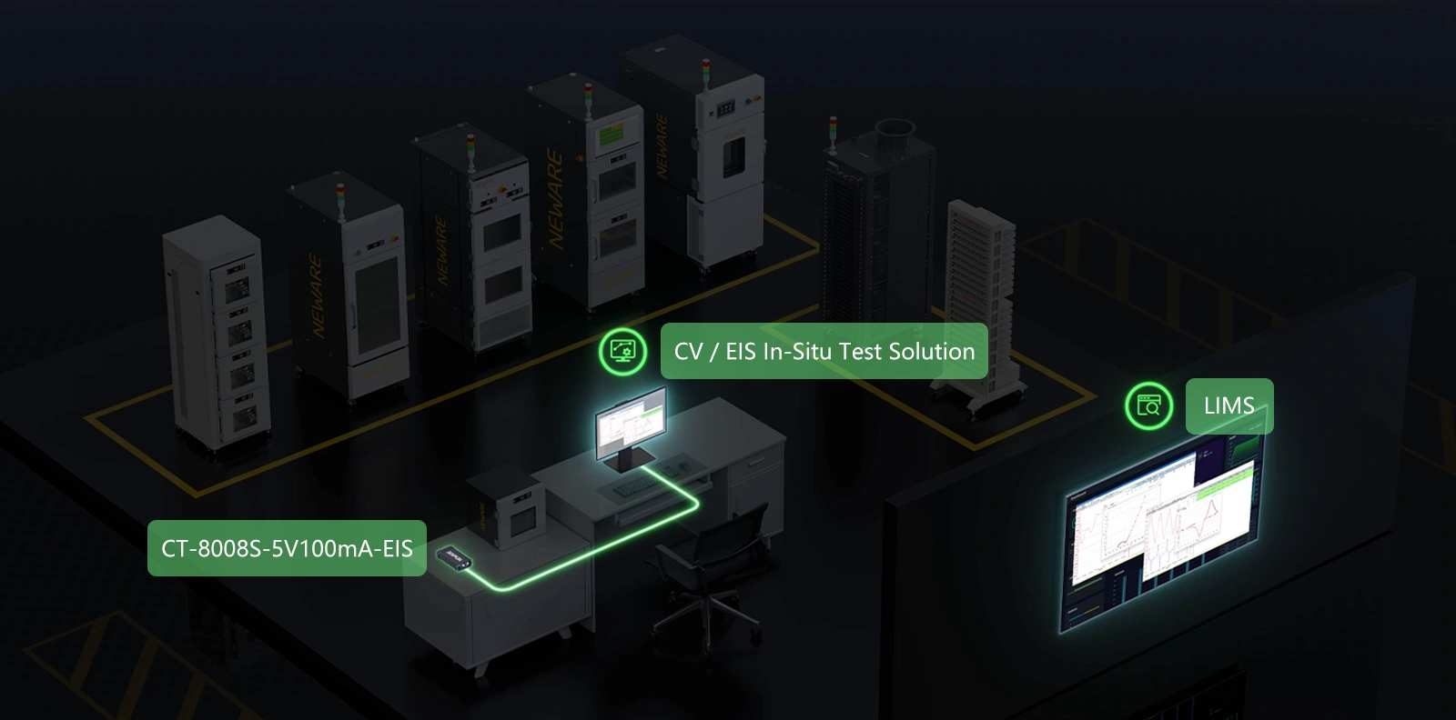
Figure 3. Architecture layout of the NEWARE CV / EIS In-Situ Test Solution integrated with CT-8008S hardware.
Conclusion & technical implementation: powered by NEWARE CV / EIS In-Situ test solution
In-situ electrochemical impedance spectroscopy serves not only as a microscope for probing reaction mechanisms in frontier battery research but also as a core quantitative tool for battery enterprises to screen electrolyte additives and evaluate functional separator modifications in industrial R&D.
To meet the rigorous requirements of next-generation high-energy-density batteries for in-situ high-frequency testing, the NEWARE CT-8002S-5V100mA-EIS Battery Testing System provides a comprehensive CV / EIS In-Situ Test Solution.
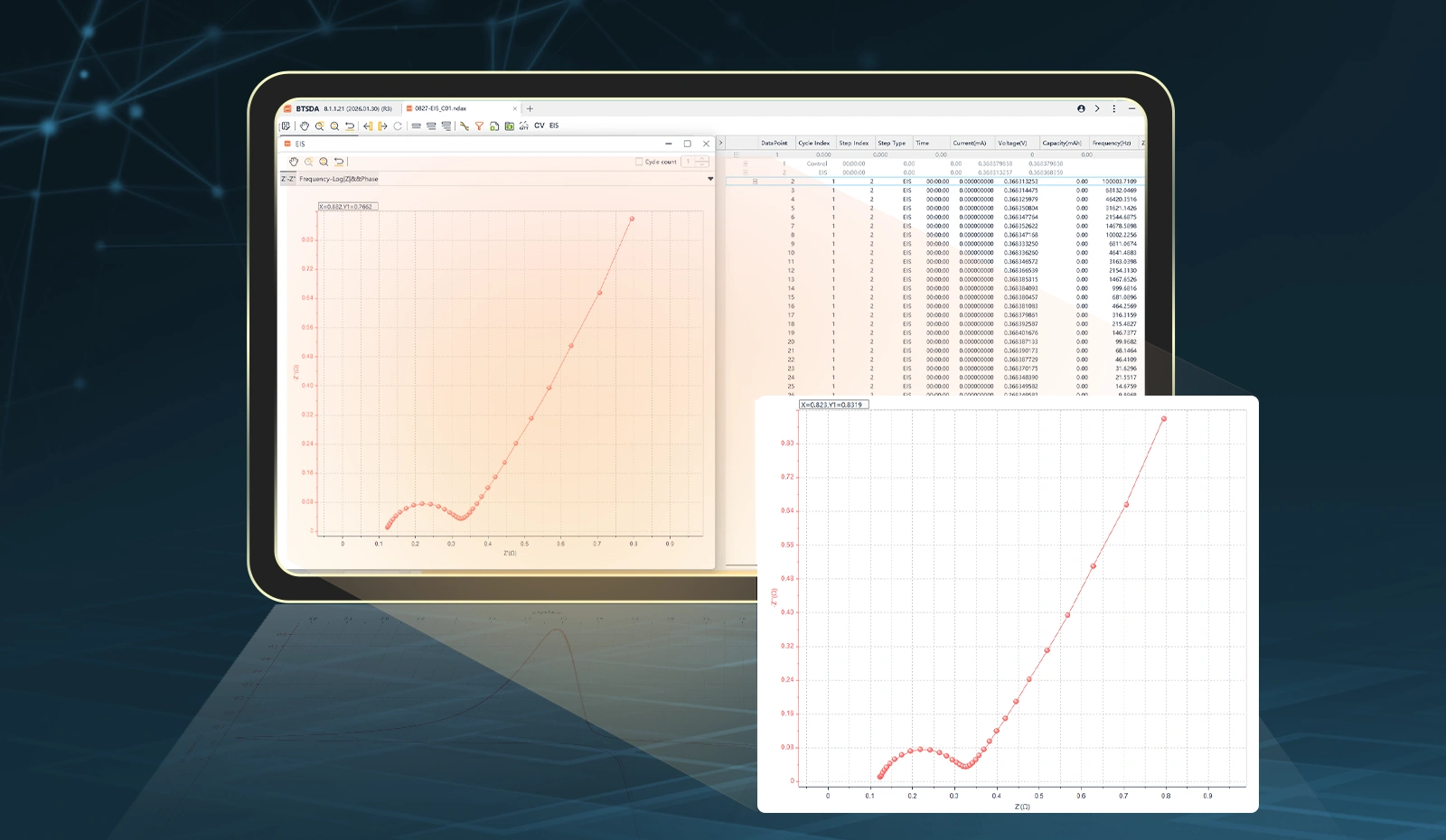
Figure 4. Software interface and real-time Nyquist plots powered by the NEWARE CV / EIS testing system.
By executing charging, discharging, cyclic voltammetry (CV), and EIS testing sequences within a single unified programmatic workflow, this solution achieves intelligent in-situ closed-loop testing without the need to reposition the battery. Its core feature—independent hardware EIS generators integrated into each individual channel—completely eliminates the high-frequency parasitic interference caused by traditional multi-channel switchers. Combined with its ±0.01% of FS ultra-high accuracy, 1000Hz high-frequency data sampling, and excellent long-term drift control, the NEWARE system empowers R&D teams to monitor the dynamic electrochemical data of polysulfide shuttling without interrupting the cycles—ultimately accelerating the development and iteration of advanced battery materials.
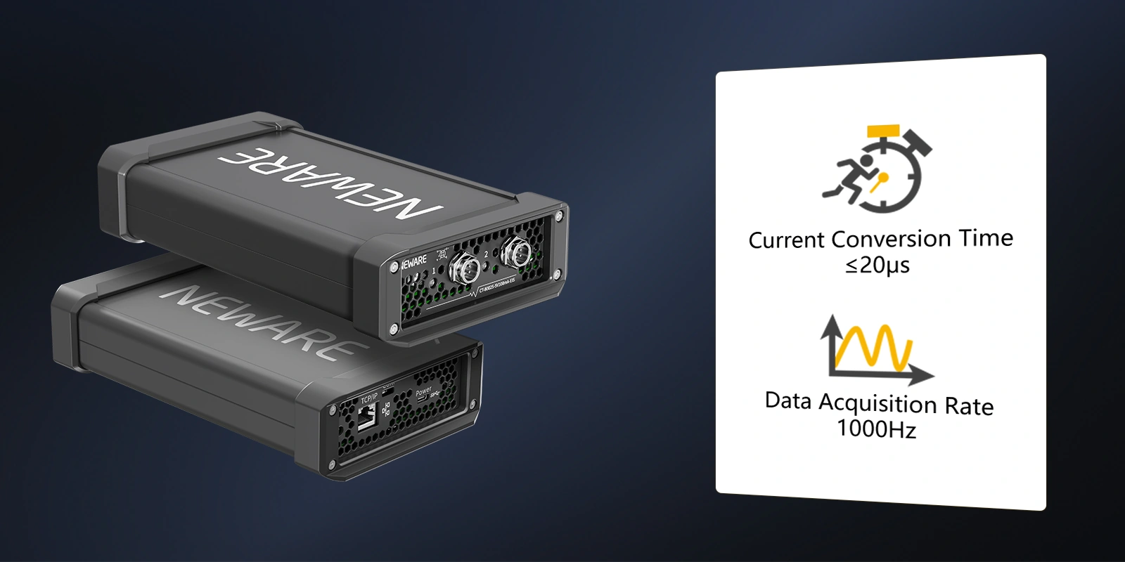
Figure 5. NEWARE CT-8002S-5V100mA-EIS Battery Testing System