Addressing EMI: Shielded Wires & Coaxial Cables ensure battery testing data reliability
In the era of energy, human activities have become intricately linked with electrical power. The battery industry has established a complete, integrated system encompassing everything from laboratory research and development to industrial production. Battery charge-discharge test equipment, serving as crucial apparatus for obtaining battery performance data, is widely used in both R&D testing and production line testing. However, the complex electromagnetic noise generated by various devices in industrial environments can interfere with measurement signals. This interference easily leads to reading drift and waveform distortion, undermining the reliability of high-precision research and testing, such as lifespan prediction and internal resistance analysis. To acquire "pure," interference-free electrical signals during testing, engineers often employ shielding wires and coaxial cables to construct a reliable physical barrier, preventing noise interference from affecting the data.
Shielding wires and coaxial cables
Although both shielding wires and coaxial cables serve an anti-interference function, their design philosophies and application levels differ.
A shielding wire is a type of cable that wraps an ordinary insulated conductor with an outer layer of metal braid or foil (the shield layer).

Figure 1 Shielding wire schematic
Its core principle utilizes the Faraday cage effect: when external electromagnetic waves attempt to interfere with the signal inside the conductor, the shield layer diverts them to ground, thereby protecting the internal signal from influence [1]. Simultaneously, it can also prevent signals within the conductor from radiating outward and interfering with other equipment. The structure of a shielding wire is relatively simple, and its cost is lower. The level of protection varies depending on the shield layer coverage and material (such as copper mesh or aluminum foil). It is primarily suitable for transmitting analog or digital signals at medium to low frequencies (typically below MHz) where the requirement for signal integrity is not extremely stringent. Examples include transmitting relatively stable DC or low-frequency AC signals like temperature and voltage.
A coaxial cable, on the other hand, is a more precisely designed cable, born for high-frequency and high-precision signal transmission.

Figure 2 Coaxial cable schematic
Its structure, from the inside out, consists of: a center (inner) conductor, an insulating dielectric layer, an outer conductor (the shield layer), and the outermost protective jacket. This "coaxial" structure is the origin of its name and the key to its excellent performance. Compared to shielding wires, the advantages of coaxial cables lie in:
Complete electromagnetic enclosure: The outer conductor and the center conductor are strictly coaxial, forming a near-perfect enclosed electromagnetic field. External interference finds it extremely difficult to penetrate, and internal signals also experience almost no leakage.
Constant characteristic impedance: By precisely controlling the diameter ratio of the inner and outer conductors and the dielectric material, coaxial cables can possess a stable and known characteristic impedance (e.g., the common 50Ω or 75Ω). This is crucial for transmitting high-frequency or fast-pulse signals, as it minimizes signal reflection and distortion within the cable.
Superior high-frequency response: Its structure enables it to effectively transmit high-frequency signals up to several GHz, with lower attenuation and distortion.
In simple terms, if signal transmission is compared to water flowing through a pipe, a shielding wire is like wrapping the pipe with soundproofing material—it blocks most environmental noise. A coaxial cable, on the other hand, is akin to a specially designed, smooth-walled pipeline that not only insulates against noise but also ensures the water flow (signal) passes through at high speed with a stable form and without turbulence.
Cable selection for different testing projects
In a battery testing laboratory, the choice between shielding wires and coaxial cables, based on different testing objectives and signal characteristics, directly determines the success of the test and the credibility of the data.
Typical battery testing projects using shielded cables
High-precision DC Internal Resistance (DCIR) test: This test calculates internal resistance by applying a brief, high-current pulse and measuring the voltage response. Although it is a DC pulse, its leading edge is steep and contains rich high-frequency components. Using a shielded cable can effectively suppress interference from environmental power frequency (50/60Hz) and its harmonics on the minute voltage measurements (often at the microvolt to millivolt level), ensuring the accuracy of the internal resistance calculation.
Long-Term cycle life and capacity test: Over charge-discharge cycles lasting months or even years, the testing equipment continuously monitors the battery's voltage and current. Shielded cables can prevent transient electromagnetic pulses generated by nearby motor startups/stops or relay operations from causing spike noise in long-term data trends. This safeguards the smoothness and authenticity of the capacity fade curve and coulombic efficiency calculations.

Figure 3 Long-term cycling performance curve at a current density of 1 A/g [2]
Multi-Channel temperature and voltage monitoring: In large module or battery pack testing, it is necessary to synchronously acquire temperature and voltage data from dozens or even hundreds of points. These signals change slowly, but the channels are dense and the wiring is complex, making them highly susceptible to cross-interference. Using shielded cables or ribbon cables is an essential measure to ensure the independence of each channel's signal, protecting them from the influence of adjacent channels or the environment.
Core testing projects requiring coaxial cable connections
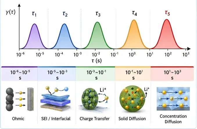
Electrochemical Impedance Spectroscopy (EIS) Testing: This is the most demanding test in terms of cable requirements, bar none. EIS analyzes the internal kinetic processes of a battery by applying a sinusoidal perturbation signal with a frequency ranging from several millihertz to several megahertz and measuring its response. The validity of the entire test is built upon a pure excitation signal and a distortion-free response signal. The constant impedance and perfect shielding of a coaxial cable ensure the complete transmission of high-frequency signals, preventing signal reflections at the cable ends from forming standing waves that interfere with measurements. It is the only viable choice for obtaining accurate and reproducible Nyquist Plots.

Figure 4 EIS Nyquist plots of NCM cathodes with varying Ni contents [3]
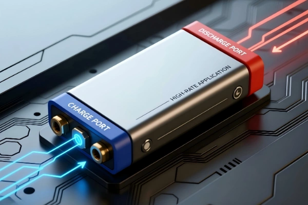
High-Frequency Pulse Testing and HPPC Testing: Hybrid Pulse Power Characterization (HPPC) testing involves a series of high-frequency charge and discharge pulses used to evaluate a battery's power performance. The rise and fall times of these pulses are extremely short (down to the millisecond level), containing rich high-frequency components. Only coaxial cables can ensure that these pulse waveforms are transmitted without distortion, thereby enabling the accurate calculation of the battery's dynamic power boundaries.
High-Precision Coulombic Efficiency (CE) Testing: When studying advanced systems like lithium-metal batteries, it is necessary to measure changes in coulombic efficiency to the fourth or even fifth decimal place. Any slight deviation in current measurement can render the conclusions unreliable. Using a coaxial cable to connect the current sensor or directly interface with the testing equipment maximizes the isolation from external interference on the minute current signals. This provides a guarantee for the precise evaluation of "first coulombic efficiency (FCE)" and the efficiency of each subsequent cycle.
Maintenance and care: Extending the lifespan of precision cables
Precision cables are a vital component of testing equipment, and their performance degradation can directly lead to measurement errors. Standardized maintenance and care are of paramount importance:
Connector Protection: Connectors on coaxial cables, such as BNC and SMA, have precise interfaces. It is strictly prohibited to pull on the cable itself to disconnect the plug. During use, align the threads or latch, and tighten or insert the connector fully to ensure impedance continuity. When not in use, attaching dust caps is recommended.
Bending Radius: It is crucial to avoid sharp bends or tight-radius bending of cables, especially coaxial cables. This can cause deformation of the internal structure, alter the characteristic impedance, and even damage the center conductor. During operation, maintain a natural curve, and the minimum bend radius should generally not be less than 5 to 10 times the cable's diameter.
Avoid Crushing and Abrasion: During cable routing, use cable conduits or ties to secure them properly. This prevents the cables from being crushed by heavy objects or subjected to prolonged friction against sharp edges, which could damage the shielding layer and the outer protective jacket.
Regular Inspection: Conduct regular inspections of the cable's exterior for any damage, deformation, and check the connectors for oxidation or looseness. For critical testing systems, network analyzers or Time Domain Reflectometers (TDR) can be used periodically to check the impedance continuity and signal attenuation of coaxial cables.
Battery testing: Shielded & Coaxial Cables for precise, reliable data
Utilizing shielded cables and coaxial cables with battery testers facilitates the acquisition of more precise test data. For routine medium-to-low frequency battery testing, shielded cables can be employed to suppress interference. For high-frequency testing, such as Electrochemical Impedance Spectroscopy (EIS), the use of high-quality coaxial cables is essential to obtain credible and reliable EIS data. Furthermore, coaxial cables should serve as the standard configuration for high-frequency HPPC pulse testing and for advanced materials research that demands extreme current measurement precision.
Reference
[1] Vance E F. Shielding effectiveness of braided-wire shields[J]. IEEE Transactions on Electromagnetic Compatibility, 1975 (2): 71-77. DOI: 10.1109/TEMC.1975.303389
[2] Wang Y Y, Hou B H, Guo J Z, et al. An ultralong lifespan and low-temperature workable sodium-ion full battery for stationary energy storage[J]. Advanced Energy Materials, 2018, 8(18): 1703252. DOI: 10.1002/aenm.201703252
[3] Lee W, Muhammad S, Kim T, et al. New insight into Ni-rich layered structure for next-generation Li rechargeable batteries[J]. Advanced Energy Materials, 2018, 8(4): 1701788. DOI: 10.1002/aenm.201701788