What does DCIR means?
Direct Current Internal Resistance (DCIR) refers to the ratio of the voltage change to the corresponding discharge current change of a battery under operating conditions. It can be measured by battery testing equipment under specific settings and is a critical parameter for evaluating electrode materials. The unit of DCIR is typically Ohms (Ω), also abbreviated as DCR. In battery research and applications, internal resistance serves as a key indicator for assessing battery performance and health status. It directly impacts discharge capability, energy efficiency, and service life. Understanding the concept, measurement methods, and influencing factors of DCIR is essential for optimizing battery design and enhancing performance.
Principles of DCIR Testing
DCIR generally consists of two components:
Ohmic Resistance (e.g., resistance from electrode materials, conductive additives, current collectors)
Polarization Resistance (e.g., charge transfer resistance, electrolyte resistance).
Ohmic resistance is the inherent physical resistance within the battery, including contributions from electrode materials, electrolyte, current collectors, and conductive additives. It primarily relates to material conductivity, contact resistance, and geometric structure.
Polarization resistance arises from electrochemical reactions and reflects the difficulty of charge transfer and ion diffusion during current flow. It typically increases with higher current density and becomes particularly pronounced during high-rate discharge.
Voltage changes over different timescales correspond to distinct resistance components:
Voltage shifts caused by ohmic resistance respond instantaneously to current steps.
Polarization voltage exhibits a delayed response.
Thus, shorter timescales are preferred for calculating ohmic resistance. Limited by testing equipment’s minimum sampling time (≥10 ms) and current stabilization requirements, the resistance derived from 10-ms voltage changes is considered the ohmic resistance.
For timescales >10 ms, the measured resistance includes:
SEI film resistance
Polarization effects (ordered by response speed: SEI resistance → electrochemical polarization → concentration polarization).

In this study, voltage/current sampling was set to 1 second. Therefore:
1-second resistance includes ohmic resistance + SEI impedance + partial polarization resistance.
The difference between 1s-resistance and 10ms-resistance primarily represents electrochemical polarization + SEI impedance.

Subtracting 1s-resistance from 60-second resistance yields the 60s polarization resistance, which mainly reflects concentration polarization.
s%7D%7D%20%3D%20%5Cfrac%7B%5CDelta%20V_%7B60s%7D%7D%7B%5CDelta%20I%7D%20-%20%5Cfrac%7B%5CDelta%20V_%7B1s%7D%7D%7B%5CDelta%20I%7D)
Theoretically, smaller measurement currents minimize polarization interference. However, battery resistance itself is very small (milliohm level). Excessively low currents introduce measurement errors due to instrument precision limitations. Thus, a balance must be struck between instrument accuracy and polarization effects.
Additionally, DCIR is influenced by:
State of Charge (SOC): Resistance is typically higher at high/low SOC and lower at mid-SOC ranges.
Current density: Higher current density intensifies polarization, increasing DCIR.
DCIR Test Setup
Test Instrument Introduction
Charging Modes: Constant current (CC), constant voltage (CV), constant current-constant voltage (CC-CV), and constant power (CP) charging. Stop conditions include voltage, current, relative time, capacity, energy, or -△V (voltage increment).
Discharging Modes: Constant current (CC), constant voltage (CV), constant current-constant voltage (CC-CV), constant power (CP), and constant resistance (CR) discharging. Stop conditions include voltage, current, relative time, capacity, or energy.
Pulse Mode: Supports CC or CP charging and CC or CP discharging pulses. Minimum pulse width is 500 milliseconds. A single pulse step supports up to 32 distinct pulses and allows continuous switching between charge and discharge within one step. Stop conditions are voltage or relative time.
DC Internal Resistance (DCIR) Test: Supports custom point selection for DCIR calculation.
Cycle Testing: Cycle range: 1~65,535 cycles; Steps per single cycle: 254.
Nested Cycles: Features nested looping functionality, supporting up to three levels of nesting. For more detailed test functionalities, consult NEWARE technical staff.
Test Parameter Configuration
For standard battery cells, the measurement current is typically set at 5C-10C. However, since the polarization resistance of lithium batteries is influenced by the applied current magnitude, the DCIR method employs short excitation durations and high currents to minimize this effect. Taking LIBs as an example, the detailed procedure setup is as follows:

Figure 2: Activating the DCIR calculation function in NEWARE BTSDA software
Click "Calculate All Adjacent Steps". After confirming the sampling point selection method, click "OK" to generate results:

Figure 3: Step demonstration diagram
Additionally, in Figure 3, you may select the option "Calculate DCIR Using Adjacent Steps Matching the Following Combination Patterns". This allows configuration of nine step types: Constant Current (CC) Charge, CC Discharge, Constant Voltage (CV) Charge, Rest, CC-CV Charge, Constant Power Discharge, Constant Power Charge, Constant Resistance Charge, and Constant Resistance Discharge. Crucially, steps must be adjacent to form valid combinations - non-adjacent steps will fail calculation. For example: Selecting a CC Charge step followed by a CC Discharge step → Clicking "Add Combination" will populate the designated field with the "CC Charge → CC Discharge" workflow sequence.

Note: Steps must be adjacent to form valid combinations.
Example workflow: Select CC Charge → CC Discharge → Click "Add Combination". The "CC Charge → CC Discharge" pair will appear in the blank box.
Application Scenarios
DCIR serves as a critical indicator of battery performance and health status, directly impacting energy efficiency, discharge capability, and service life. By understanding DCIR fundamentals, measurement methodologies, and influencing factors, researchers and engineers can optimize battery system design to enhance performance and safety. Future advancements in measurement technologies and novel materials will further elevate DCIR's role in driving battery innovation. Key application scenarios include:
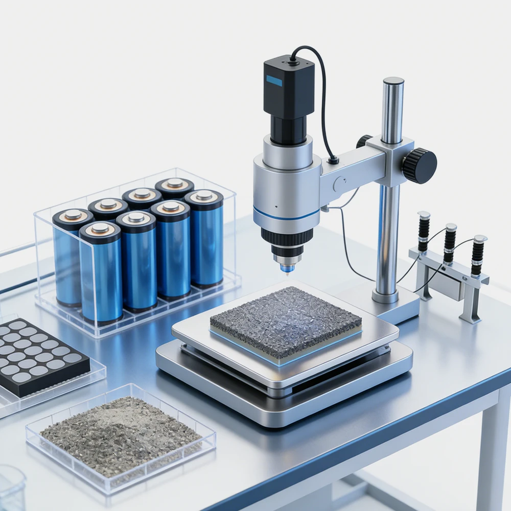
Electrode Material Design DCIR enables micro-short detection during production and serves as a primary extrinsic parameter characterizing Li-ion battery kinetic properties. When current is applied, terminal voltage undergoes rapid changes. The ratio of voltage variation to current variation yields internal resistance, guiding the development of materials with enhanced kinetic transport properties.
Battery Performance Evaluation DCIR reflects internal side reactions, active material decomposition, structural degradation, electrode delamination, and SEI film growth. This assists in analyzing energy storage mechanisms and evaluating performance under various conditions (e.g., system SOC, input/output capabilities).
Cycle Life Prediction DCIR measurements reveal material stability during charge/discharge cycles, providing critical insights into aging mechanisms and enabling accurate cycle life projections.
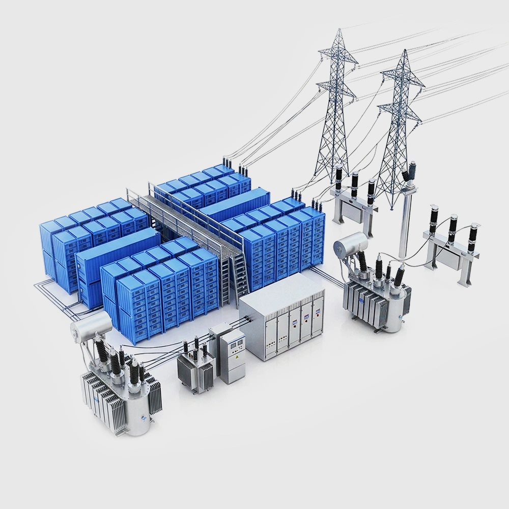
Battery Recycling & Reuse Elevated temperatures accelerate parasitic reactions and electrode degradation, causing DCIR to increase rapidly. Measuring DCIR in retired batteries helps assess residual value and reuse potential.
State-of-Health Monitoring Real-time tracking of DCIR evolution during operation enables continuous assessment of performance degradation and health status.
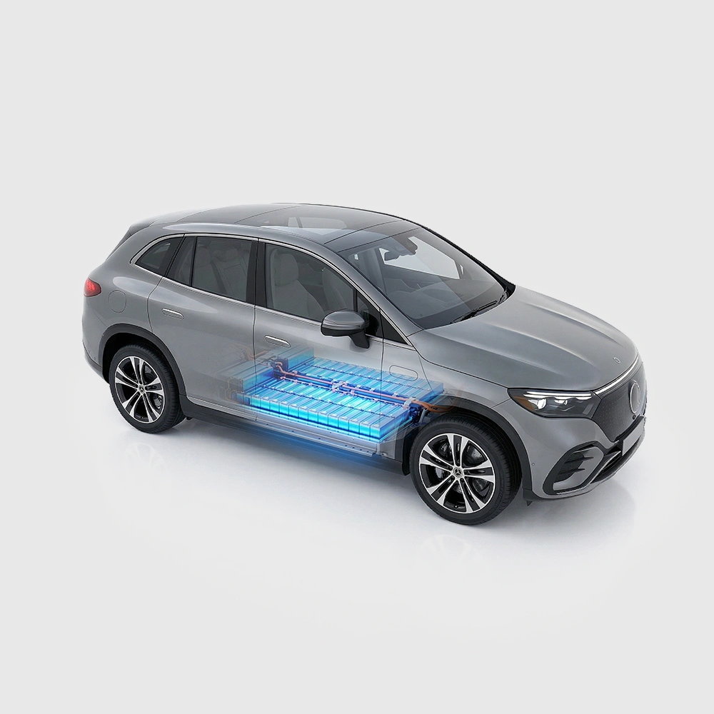
Equipment Development For large-scale battery packs (e.g., EV power systems), AC impedance testing is often infeasible due to equipment limitations. DCIR provides a practical alternative for pack-level characterization.
These applications demonstrate DCIR's multifaceted impact on battery technology. As a pivotal performance parameter with profound implications, DCIR testing remains indispensable for electrode material assessment and system optimization.