Introduction
After decades of continuous improvements in battery materials by researchers, the capacity and performance of portable mobile phone batteries have been steadily enhanced. Batteries have transitioned from nickel-cadmium and nickel-metal hydride to the now most commonly used lithium-ion batteries. The batteries in our current phones are precisely lithium polymer batteries. Their capacity improvements are generally achieved through the following methods:
Improved conductivity: Research and development of high-strength, high-conductivity electrolyte membranes.
Structural improvements: Development of special polymer frameworks to enhance ionic conductivity.
Additive enhancements: Development of various new additives to improve battery performance.
Cathode improvements: Development of new co-doped cathode materials, transitioning from early lithium cobalt oxide cathodes to ones similar to those used in ternary lithium batteries.
Anode improvements: Development of new silicon-carbon composite anodes.
The first four improvement methods had already been relatively maturely researched in earlier years. The fifth method is now the most frequently highlighted aspect in battery segments during mobile phone launch events. Over the past five years (Table 1), the fastest battery capacity growth occurred in the last two years, with some brand's phone batteries increasing directly from 4610mAh to 7000mAh (Xiaomi and OPPO), an increase of over 50%. A significant part of this improvement stems from advancements in anode materials.
| Brands | Samsung | Apple | Xiaomi | OPPO | VIVO | Unit |
| Year | Battery capacity | |||||
| 2021 | 4000 | 3227 | 4500 | 4500 | 4400 | (mAh) |
| 2022 | 3700 | 3279 | 4500 | 4800 | 4500/4810 | |
| 2023 | 3900 | 3349 | 4610 | 4800 | 5000 | |
| 2024 | 4000 | 3561 | 5400 | 5000/5630 | 5800 | |
| 2025 | 4000 | 3692 | 7000 | 7025 | 6040 | |
Table 1 battery capacity changes in major smartphone brands (past five years), and only the standard version is counted
In this article, we will provide a detailed explanation of the reasons behind the expansion of silicon-carbon anodes, summarize several methods to mitigate this issue, and highlight a commonly overlooked drawback of using silicon-carbon anodes in smartphones—one that manufacturers have not publicly addressed. Additionally, you will learn about the equipment we offer for testing 3C batteries at the end of the article.
Silicon-carbon anodes
Conventional lithium polymer batteries typically use graphite for the anode, which has a theoretical specific capacity of 372 mAh/g. In contrast, silicon has a very high theoretical specific capacity of 4200 mAh/g. This means that if silicon could completely replace graphite, a significant amount of volume and mass could be saved and allocated to the cathode, thereby increasing the overall capacity of the battery. However, silicon undergoes a volume expansion rate of up to 300% during charge and discharge cycles, preventing it from fully replacing graphite.
Silicon-carbon anodes represent an advanced material for lithium-ion batteries, combining the high capacity of nano-silicon with the structural stability of carbon materials. By compositing silicon particles with a carbon matrix, these anodes not only enhance the battery's energy density but also utilize carbon's buffering effect to suppress silicon's volume expansion during cycling, preventing electrode pulverization. Currently, the silicon content in smartphone batteries has been increased to approximately 15%, making this technology essential for developing high-capacity batteries.
Reasons for the expansion of silicon-carbon anodes
The primary cause is related to the lithium storage mechanism of silicon [1]. As observed in the Li-Si phase diagram (Figure 1a), lithium-silicon alloys can form multiple phases with different compositions, such as Li12Si7, Li7Si3, Li15Si4, and Li22Si5. The charge-discharge voltage profile of silicon shows voltage plateaus corresponding to these phases at approximately 0.33V, 0.29V, 0.16V, and 0.04V (Figure 1b). This indicates that during charging and discharging, the formation of these various alloy phases—which are less dense than pure silicon—occupies more space and disrupts the original stable structure.
Furthermore, a single silicon atom can bond with up to 4.4 lithium ions (forming Li22Si5), whereas in graphite, six carbon atoms are required to host just one lithium ion (forming LiC6). This exceptionally high lithium storage capability allows a massive influx of lithium ions, leading to the creation of new, less densely packed alloy phases. This process significantly increases the lattice constant of silicon. Macroscopically, this manifests as severe volume expansion.

Figure 1 (a) phase diagram of Li-Si system [2], (b) Si electrochemical lithiation/delithiation curves [3]
In simple terms, the reason for silicon's expansion can be compared to a sponge absorbing water: its volume changes dramatically. After releasing the lithium ions, similar to a sponge being repeatedly dehydrated, it suffers irreversible damage like structural loosening and cracking.
Methods for improving silicon-carbon anodes
Nanostructuring of silicon materials: After being nanostructured, silicon materials can provide more voids to accommodate volume expansion, reduce internal mechanical stress, and prevent material fracture. The nanostructure shortens the transport pathways for ions and electrons, facilitating faster charging and discharging rates. Common strategies for nanostructuring silicon materials include: mixing nanoscale spherical silicon particles with carbon materials, directly growing silicon nanowires, and depositing two-dimensional thin films on current collectors.
Carbon composite and structural design: Various carbon materials combined with silicon (such as amorphous carbon, porous carbon, hollow carbon shells, etc.) can provide a continuous and flexible conductive network while mitigating the volume expansion of silicon. They also isolate direct contact between silicon and the electrolyte, promoting the formation of a stable SEI layer. Currently, primary carbon sources include graphite, graphene, diamond-like carbon, carbon nanotubes, etc., while novel carbon sources include biomass-derived nanostructured carbon, carbon derived from carbon-containing gases, and metal-organic frameworks (MOFs). This composite and structural design is typically built upon nanostructured silicon and is a commonly used solution in commercial silicon-carbon anodes (Figure 2).

Figure 2 composite structures of three carbon sources with silicon nanoparticles: (a) Graphite [4], (b) Graphene [5], (c) Graphdiyne[6]
Porous structure design: Using acid etching methods to prepare porous silicon frameworks can create internal buffer spaces within the material, thereby alleviating the mechanical stress caused by silicon's volume expansion. Additionally, porous silicon has a larger specific surface area, which is conducive to rapid charging and discharging. However, since direct contact with the electrolyte can lead to numerous side reactions, porous silicon usually also requires combination with carbon materials.
Optimization of binders and electrolyte additives: The use of self-healing, highly elastic polymer binders can tightly adhere silicon during its volume expansion and contraction, preventing the detachment of electrode materials. The electrolyte additive fluoroethylene carbonate (FEC) can form a more flexible and stable SEI layer on the silicon surface, which is less prone to cracking during silicon's expansion and contraction. This avoids continuous SEI layer growth and enhances the battery's cycle life.
Through various improvement methods mentioned above, silicon-carbon anodes have now achieved high performance levels. The silicon content in mobile phone battery anodes has increased from an initial 6% to 15%, significantly enhancing both energy density and capacity.
Others about mobile phone batteries
In addition to capacity improvements, mobile phone batteries have also been upgraded in terms of charging speed and cycle life. Apple's original 5V 1A (Figure 3) charger has now been upgraded to support up to 20V 2A (15V 2.67A), while some Chinese manufacturers have achieved charging power of up to 240W, with laboratory prototypes even reaching 320W fast charging.

Figure 3 Apple power adapters. Left: 5V 1A, Right: 20V 2A (15V 2.67A)
But here's something you might not know
While mobile phone battery capacity has significantly increased, the total charging time has actually become longer due to insufficient improvement in charging power. Battery testing researchers understand that during testing, the charge-discharge rate (C-rate) can be set. In this scenario, the time required to fully charge the battery is almost independent of its physical size or capacity. This is because if a 1C rate is set, the testing equipment automatically adjusts the current based on the active material content and theoretical specific capacity. Larger capacity batteries of the same chemistry will use higher currents, while smaller ones use proportionally lower currents. Since both utilize the same battery material system, their 1C charge-discharge curves and cycle life are theoretically very similar.
This demonstrates that for a larger capacity phone battery using the same material system as an older, smaller battery, the charging current can be increased. The voltage remains constant, meaning the charging power can be increased accordingly. This wouldn't necessarily harm battery life, and the full charging time could remain the same.
The fact that capacity has increased without a proportional increase in charging power indicates a decline in the battery's rate capability. Previously, a maximum charging power of 90W (with an actual peak around 60W+) corresponded to an average charge rate close to 2C (full charge in 30+ minutes). Now, the same 90W corresponds to an average rate of less than 1.2C (full charge in 50+ minutes).
Given that the cathode material hasn't changed dramatically, this limitation stems primarily from the silicon in the anode. Under high currents, the rapid insertion of lithium ions into silicon causes:
Severe mechanical stress and structural failure: The rapid volume expansion creates significant shear stress due to differential expansion rates between the surface and the core of silicon particles. This leads to particle cracking or pulverization, electrode detachment, and even damage to the current collector. Furthermore, repeated expansion and contraction can fracture the Solid Electrolyte Interphase (SEI) layer. The constant reformation of this layer consumes active lithium and electrolyte, increasing internal resistance and causing capacity fade. An excessively thick SEI layer also hinders lithium-ion transport, worsening polarization.
Significant polarization effects: The large disparity between ion diffusion speeds and electron movement, coupled with limited interfacial reaction kinetics, causes a sharp increase in concentration polarization and electrochemical polarization. This narrows the effective electrochemical window for charging and discharging and leads to prematurely reaching voltage limits, resulting in a substantial decrease in usable capacity.
Lithium metal plating (lithiation): At high currents, the rate of lithium ions migrating to the anode surface surpasses their rate of insertion into the silicon crystal lattice. Unable to embed in time, lithium ions accumulate on the surface. If the surface potential drops below 0V (vs. Li/Li+), the ions directly combine with electrons to form metallic lithium, which deposits on the anode surface. This not only consumes active lithium and electrolyte but also poses a severe safety risk. The deposited lithium can grow into dendrites that may penetrate the separator, causing an internal short circuit, thermal runaway, and potentially even explosion.
These drawbacks make it difficult for phones using silicon-carbon anodes to maintain good cycle life under higher power charging and discharging. Therefore, after increasing battery capacity, various smartphone manufacturers have chosen to maintain the original charging power. This essentially reduces the average C-rate of the battery's charge and discharge cycles to ensure the phone battery's service life. After all, consumers might accept the battery life dropping from an initial ten hours to nine hours after one year of use, but they would not tolerate it dropping to six hours after just a few months.
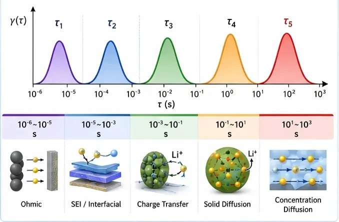
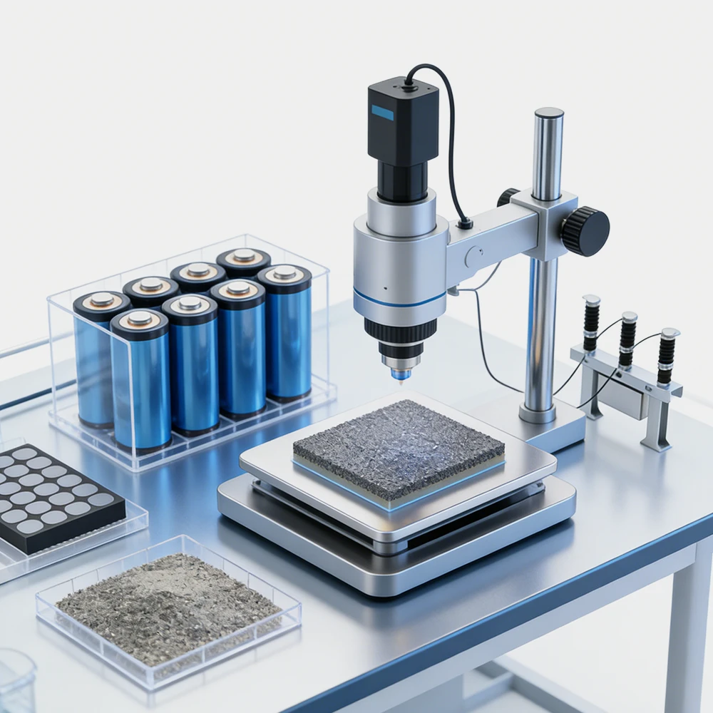
Like conventional batteries, mobile phone batteries also require a series of tests, including cycle testing, CV testing, EIS testing, GITT testing, DCIR testing, rate capability charge-discharge testing, and long-term cycle aging testing, among others. NEWARE 3C test system (Figure 4) can already be used for mobile phone battery testing, covering test conditions from 5V-30V and 6A-30A. If constant temperature testing is required, different specifications of temperature chambers can be selected for integration. Standard constant temperature chambers typically cover a range from 0℃ to 85℃, with temperature fluctuations of less than 1℃. For more specific requirements, such as low-temperature testing, the WGDW series can be selected, which covers a temperature range from –70℃ to 150℃ with fluctuations under 0.5℃. Multi-zone temperature chambers are also available for simultaneously testing battery performance at different temperatures (the WHW series supports up to four zones, the WGDW series supports up to two zones). If testing space is limited, PC all-in-one testing system is an option, saving over 56% of floor space (excluding the computer's footprint).

Figure 4 NEWARE 3C testing system,all-in-one testing system and PC all-in-one tesing system
If you want to learn about the development history of mobile phone batteries, you can read History of Mobile Phone Battery Development: "Shrinking Downsides, Growing Upsides"
References
[1] Jin B, Liao L, Shen X, et al. Advancement in Research on Silicon/Carbon Composite Anode Materials for Lithium-Ion Batteries[J]. Metals, 2025, 15(4): 386.
[2] Wu H, Cui Y. Designing nanostructured Si anodes for high energy lithium ion batteries[J]. Nano today, 2012, 7(5): 414-429.
[3] Park C M, Kim J H, Kim H, et al. Li-alloy based anode materials for Li secondary batteries[J]. Chemical Society Reviews, 2010, 39(8): 3115-3141.
[4] Yu P, Li Z, Han M, et al. Growth of vertical graphene sheets on silicon nanoparticles well-dispersed on graphite particles for high-performance lithium-ion battery anode[J]. Small, 2024, 20(17): 2307494.
[5] Zhang Q, Yang Y, Wang D, et al. A silicon/carbon/reduced-graphene composite of honeycomb structure for high-performance lithium-ion batteries[J]. Journal of Alloys and Compounds, 2023, 944: 169185.
[6] Li L, Zuo Z, Shang H, et al. In-situ constructing 3D graphdiyne as all-carbon binder for high-performance silicon anode[J]. Nano Energy, 2018, 53: 135-143.