Introduction: This document describes the steps for configuring channel mapping for the pressure auxiliary unit(s).
1. Operating environment
1.1 Hardware connection
Ethernet cable connection steps:
(1) Connect the control unit to the tester using an Ethernet cable.
(2) Use Ethernet cables to separately connect the PC, control unit, and pressure auxiliary channel to the switch.
")
Figure 1-1
The channel cable is soldered with banana plug. Insert the banana plug to the center of the solid state battery mould. Underneath the mould, there’s a pressure sensor with five wires. Insert the wires into the auxiliary pressure unit as shown in Figure 1-2.
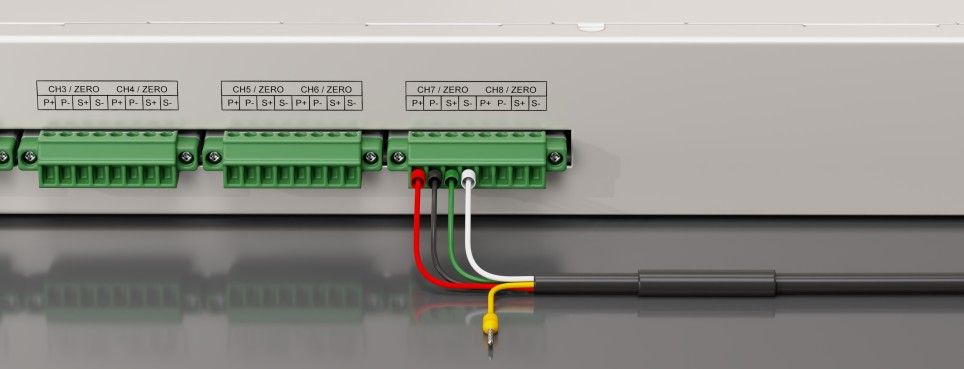
Figure 1-2
1.2 Environment configuration
Open the Control Panel on the computer, find Network and Internet, select Network and Sharing Center, find “Ethernet” and right-click to select “Properties”, as shown in Figure 1-3.
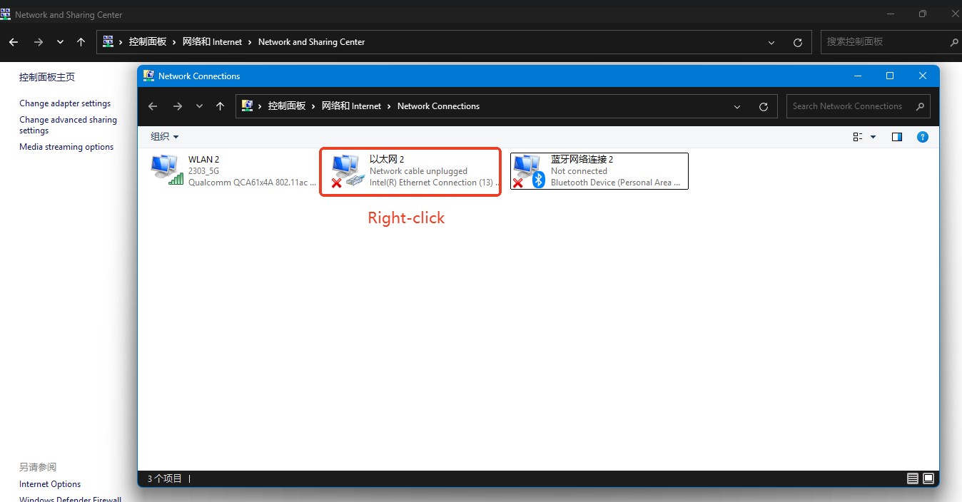
Figure 1-3
Then, in the pop-up window, select “TCP / IPv4” and click “Properties.” In the advanced settings window, add an IP address in the format 192.168.1.xxx (Make sure the first three octets of the IP addresses for the pressure-aux channel, the PC, and the control unit are identical—e.g., 192.168.1.xxx).
")
Figure 1-4
2. Software configuration methods
The pressure aux supports two-channel mapping methods, as shown in Table 2-1.
Table 2-1
Mapping method | Equipment to be configured | Configuration method |
CAN communication sampling point mapping | Pressure auxiliary channel | Web page |
External device converter mapping | Control unit | Web page |
Users can choose one of them according to their own needs.
3. CAN communication sampling point mapping
3.1 Pressure auxiliary CAN configuration
3.1.1 Set data transmission format
Enter the IP address (e.g., 192.168.1.152) of the pressure auxiliary unit (usually found on the device’s label) into your browser. Under the “Communicate” tab, configure the DBC information: set “Message No.” to 1 and “Pack Format” to “Pressure.”
")
Figure 3-1
3.1.2 Set up the control unit to connect to
Add the IP address of the control unit (e.g., 192.168.1.196) and the port number (18001 to 18008 correspond to CAN numbers 1 to 8, respectively), check the corresponding row, and click “Set” as shown in Figure 3-2. This setting will take effect after the pressure auxiliary unit is restarted.
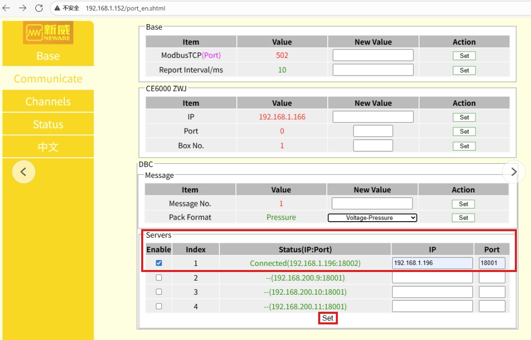
Figure 3-2
3.2 BTS Configuration
3.2.1 Right-click menu configuration
Click “Set” in the main menu, then click “System settings” in the submenu, as shown in Figure 3-3.
")
Figure 3-3
Click “Display settings,” then find “Auxiliary channels CAN Communication sampling point mapping” in the “Right-click menu function” section and save. As shown in Figure 3-4.
")
Figure 3-4
3.2.2 Configuration mapping
Right-click the channel and select “Auxiliary channels CAN communication sampling point mapping” from the context menu, as shown in Figure 3-5.
")
Figure 3-5
In the Auxiliary channels CAN communication sampling point mapping interface, select the channel number, right-click and choose “Custom CAN-1,” then configure “Sampling point-1.” See Figure 3–6 for details.
")
")
Figure 3-6
3.2.3 Configure DBC
At the bottom of the Start Workflow page, select “DBC,” click “DBC edit,” open the pre-edited DBC file, and click OK as shown in Figure 3-7&8.
")
")
")
Figure 3-7
")
Figure 3-8
Note: Port 18001 on the intermediate unit corresponds to CAN ID 1 in BTS, 18002 to 2, …, 18008 to 8.See Figures 3-9, 3-10, and 3-11 for details.
")
Figure 3-9
")
Figure 3-10
")
Figure 3-11
3.2.4 View data
Start the test—the pressure value will appear on the main channel.
")
Figure 3-12
Right-click the main channel and select “View data” to open BTSDA and review the pressure data.
")
")
Figure 3-13
4. External device converter mapping
4.1 Control unit configuration
Enter the control unit IP address in the browser, log in, select “CommonTransfer” on the “Auto machine 1 IP & Port” page, enter “127.0.0.1” for the IP address, enter “18050” for the port, and enter ‘1’ for the last item. Click “Submit” as shown in Figure 4-1. Restart the control unit for the changes to take effect.
")
Figure 4-1
The account for logging into the control unit is “neware” and the password is “xinwei”.
4.2 BTS external communication device configuration
4.2.1 Viewing external general device ports
Enter the IP address (e.g.,192.168.1.153)of the pressure auxiliary unit in the browser, click “Communicate” on the left side to view the ports of the pressure collection box, as shown in Figure 4-2.
")
Figure 4-2
4.2.2 Right-click menu settings
Similar to 3.2.1 Right-click menu configuration, select “External device converter mapping” in Set - System settings - Display settings - Right-click menu function, as shown in Figure 4-3.
")
Figure 4-3
4.2.3 External device converter settings
Click “Set” on the main menu, then click “External device converter settings” in the submenu, as shown in Figure 4-4.
")
Figure 4-4
Then, place the “Aux_ext.xml” file in the project folder under the root directory of the pop-up window, as shown in Figure 4-5. In the figure, it is placed in the ...\AdapterFileManager\Test directory.
")
Figure 4-5
After placing it inside, click “Set” on the main menu, then click “External device converter settings” in the submenu. The file list in the pop-up window will display “Aux_ext.xml.”
Then, click the PLC list, enter the IP address of the pressure sensor, and the Modbus TCP port seen in 4.2.1 View External Universal Device Ports, then click “Send settings” as shown in Figure 4-6.
")
Figure 4-6
Then, in the pop-up window, check the converter, select the pressure collector PLC (if the IP and port are incorrect, they need to be modified here), and click OK, as shown in Figure 4-7.
")
Figure 4-7
Note: Sending external device converter configuration files to the control unit will automatically restart the device, which may affect channels that are currently in use. Please wait until all channels are inactive before sending the files.
The parameters will then be sent to the control unit, which will automatically restart. Wait until the restart is complete.
4.2.4 External device converter mapping
Right-click “External device converter mapping” in the pop-up menu, as shown in Figure 4-8.
")
Figure 4-8
In the pop-up window, select the pressure collection box channel on the left and the channel on the right, then right-click and select “Map the left selected signal,” as shown in Figure 4-9.
")
Figure 4-9
4.2.5 Importing external parameters
When starting the operation step, click the External Parameters tab in the pop-up window, then click Import, and select Pressure Display.xml, as shown in Figure 4-10.
")
Figure 4-10