1. Introduction
Metal-ion batteries experience capacity fade during long-term cycling. This capacity fade encompasses both reversible capacity loss and irreversible capacity loss. Reversible capacity loss can be recovered through low-rate charging and discharging (i.e., using low current densities). In contrast, irreversible capacity loss includes loss of active material at the cathode, loss of active material at the anode, and loss of active lithium ions. While irreversible capacity loss can be roughly estimated using half-cell analysis, fabricating half-cells is typically a destructive procedure.
The voltage differential capacity curve (dQ/dV) is an electrochemical characterization technique used to analyze the relationship between voltage and charge quantity during battery charging and discharging. The dQ/dV curve provides the derivative of voltage with respect to charge (dQ/dV), enabling the analysis of internal electrochemical reactions and physical processes within the battery. Furthermore, because distinct chemical processes exhibit varying reaction rates within specific voltage ranges, the dQ/dV curve can reveal the activation energy and reaction kinetics of different electrochemical reactions occurring inside the battery.
Differential capacity (dQ/dV) curve analysis, as an in-situ, non-destructive analytical technique, is gaining increasing attention and application due to its convenience. This article primarily introduces the testing principles, plotting methodologies, and analytical approaches for battery differential capacity analysis.
2. Principles and Methods of dQ/dV Testing
2.1 Principles
Voltage Differential Capacity (dQ/dV): dQ/dV refers to the rate of change of charge quantity (Q) within a minute voltage interval during battery charging or discharging. This value is obtained by mathematically differentiating the charge/discharge curve. Formally, it is expressed as the derivative of charge with respect to voltage:dQ/dV = I(t) / (dV/dt) where:
Q is the charge quantity (typically in ampere-hours, Ah, or coulombs, C),
V is the voltage (in volts, V),
I(t) is the current (in amperes, A) at time t.
Battery charge/discharge curves typically represent voltage as a function of charge transferred (Q). During cycling, the voltage change is often non-linear due to the superposition of multiple electrochemical reactions occurring within the battery.
Consequently, by differentiating the charge/discharge curve, the dQ/dV curve is obtained. This curve serves to elucidate the activation energy and reaction kinetics associated with distinct electrochemical processes inside the battery.

Figure 1. Charge/discharge curves and dQ/dV curves of Li-rich NCM material at different cycle numbers
As shown in Fig. 1, the voltage plateaus in the charge/discharge curves of the lithium-rich material are significantly lowered with increasing cycle number. However, the precise location of these plateaus cannot be intuitively determined from the voltage curves alone. After processing the data through differential capacity (dQ/dV) analysis, the pronounced lowering of the voltage plateaus is clearly identified in the dQ/dV curves.
2.2 Differential Capacity (dQ/dV) Testing Methodology
The battery undergoes galvanostatic (constant-current) charge/discharge cycling. The differential capacity (dQ/dV) is then calculated from the test data as the ratio of the change in capacity (ΔQ = Q₂ - Q₁) to the corresponding change in voltage (ΔV = V₂ - V₁), yielding the capacity contained per unit voltage interval. This series of calculated values is plotted to generate the curve. The x-axis of the dQ/dV curve typically represents State of Charge (SOC), capacity, or voltage, reflecting the rate of change of capacity. Regions of high rate of change appear as characteristic peaks on the curve, generally corresponding to specific electrochemical reaction processes.
Since chemical reactions are rapid, the dQ/dV curve requires high data point precision to resolve these features effectively. Consequently, the dQ/dV curve places stringent requirements on the resolution of the raw data acquisition; insufficient resolution may prevent the observation of distinct peaks. Therefore, during galvanostatic testing:
1. The current density should be minimized to reduce battery polarization.
2. The voltage sampling interval should be sufficiently small. Recommended practices include:
Setting a voltage step ΔV = 10~50 mV for data acquisition, OR
Setting a time interval Δt = 10-50 ms for data point collection.Following data acquisition, points are often filtered to achieve equal voltage intervals before plotting.
Distinction between dQ/dV Curves and Cyclic Voltammetry (CV) Curves:While dQ/dV and CV curves may appear visually similar, they differ fundamentally:
1. dQ/dV Curve:
Controlled parameter: Current (galvanostatic control).
Output: Charge passed (Q) vs. Potential (V). Current changes induce changes in charge and potential.
Peak manifestation: Requires the redox reaction to proceed to completion to fully develop peaks. Since the process occurs at constant current, the diffusion rate is constant, leading to more accurate potential resolution for phase transitions.
2. CV Curve:
Controlled parameter: Potential (potentiostatic control, linear voltage sweep).
Output: Current (I) vs. Potential (V).
Peak manifestation: Peaks arise from the relative rates of the electrochemical reaction and mass transport (diffusion). If the scan rate is too high, peaks may become broad, indistinct, shifted, or even obscured, significantly impacting their observability and position.
3.dQ/dV Testing Configuration
3.1 Introduction to Testing Instrumentation
Based on the principles and computational methods of voltage differential capacity (dQ/dV), corresponding test parameters are configured to obtain results prior to data processing.
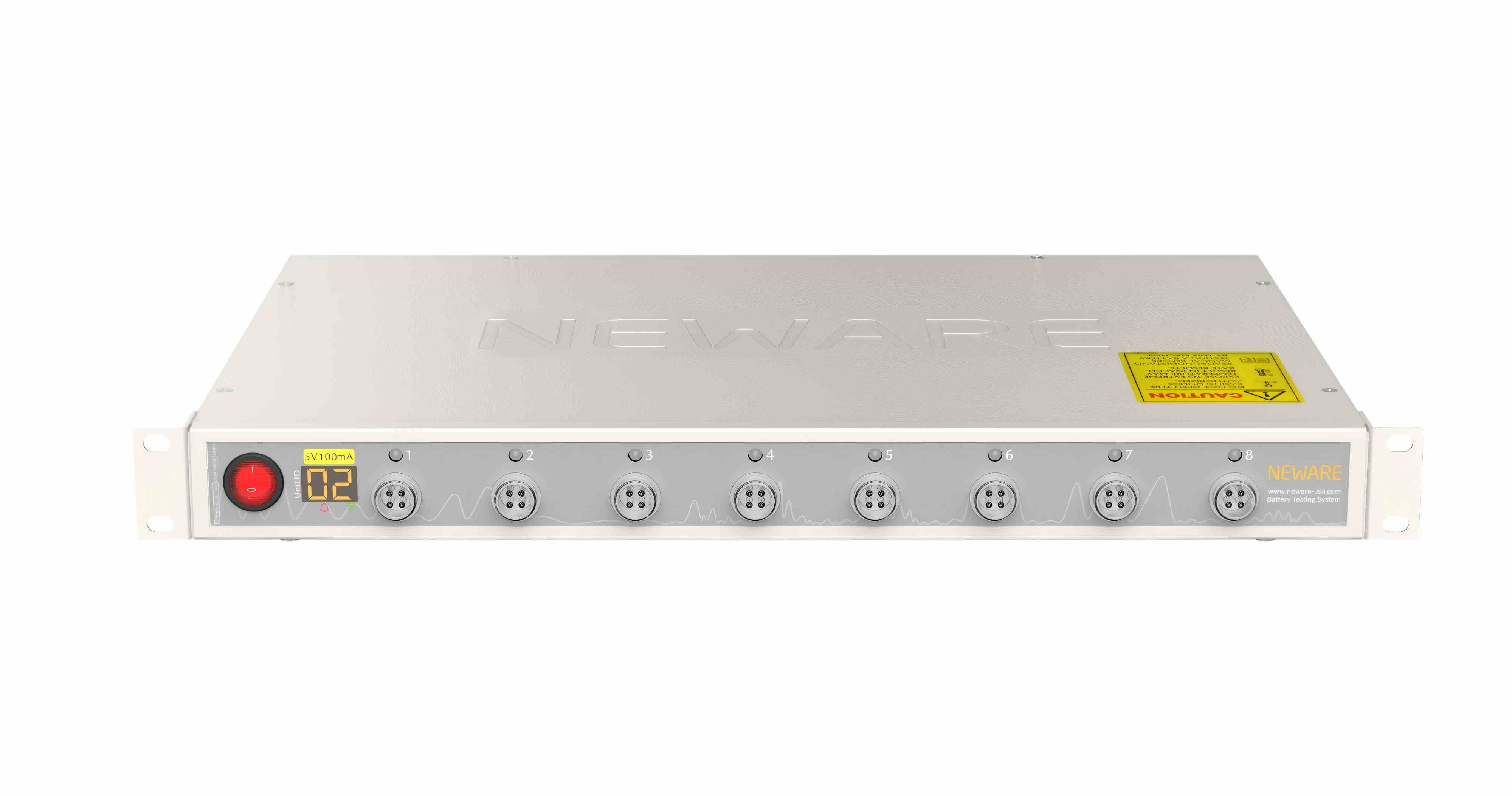
Figure 2. NEWARE Battery Testing System
The NEWARE Multi-Channel Battery Testing System (shown in Fig. 2) was selected to perform galvanostatic charge/discharge tests.
The NEWARE system integrates multiple testing methodologies, including:
GITT (Galvanostatic Intermittent Titration Technique)
Galvanostatic (CC) charge/discharge
Constant Voltage (CV) chargeAdditionally, it features built-in data processing functions for GITT analysis and dQ/dV derivation. Following the test procedure described above:
1. Configure a low current density for battery testing.
2. Directly select the dQ/dV processing function within the system.
3. Export or copy data to Origin for plotting to generate the dQ/dV curve.For comprehensive details on the NEWARE system’s capabilities, contact NEWARE Technical Support.
3.2 Test Parameter Configuration
Using an aqueous zinc-ion battery cathode material as an example, follow these steps:
1. Perform galvanostatic charge/discharge at 0.1 A/g current density.
2. Invoke the built-in dQ/dV function to process raw data.
3. Generate the dQ/dV curve.
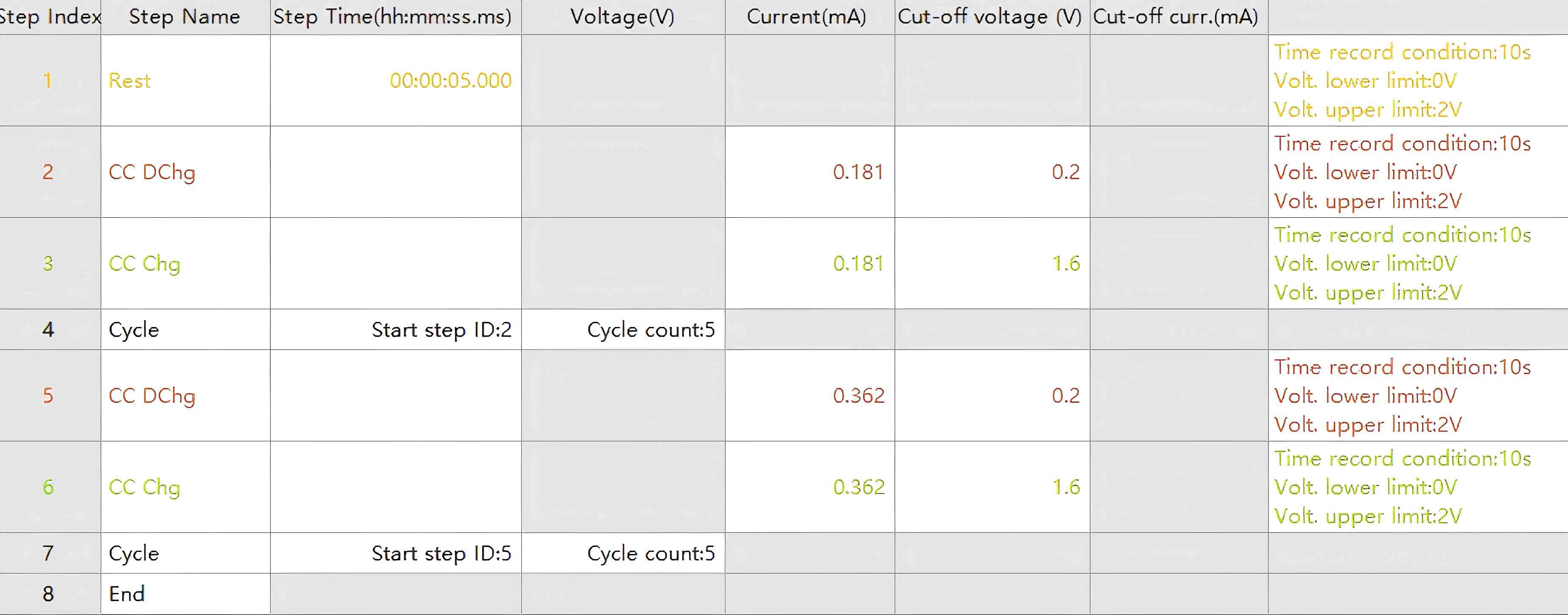
Figure 3. Test Program Parameters
After configuring according to the above test parameters, upon completion of testing, select the desired cycle number to obtain the constant-current charge/discharge curves as depicted in Fig. 4
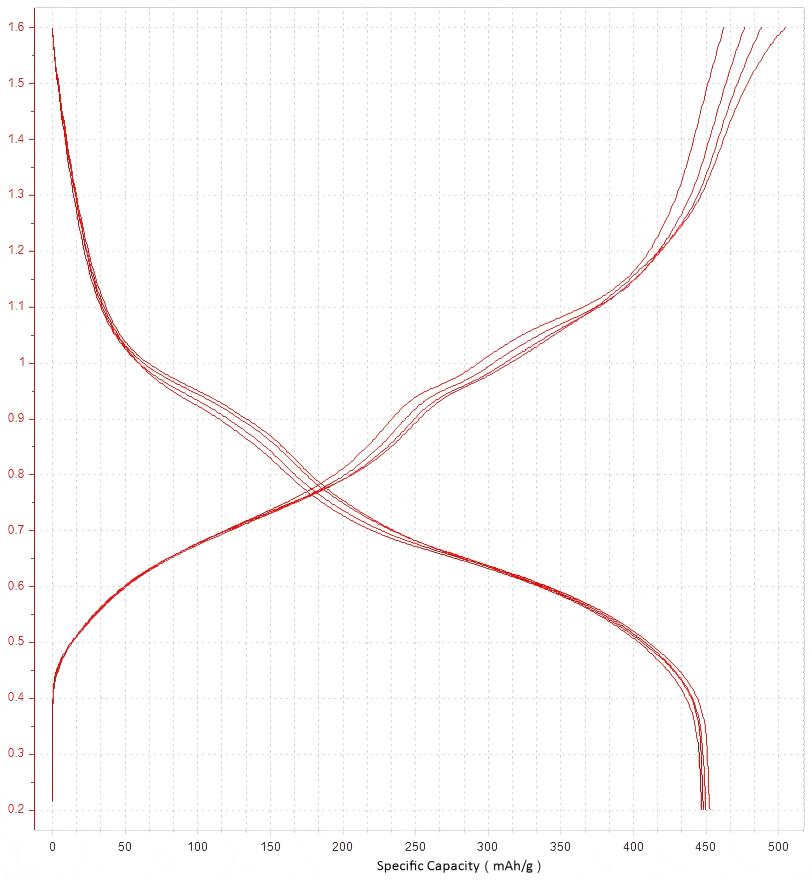
Figure 4. Constant-Current Charge/Discharge Curves
3.3 Test Data Analysis
Open the constant-current charge/discharge data obtained from the NEWARE multi-channel battery test system. Right-click on the symbol indicated in the graph and select "Curve Settings".
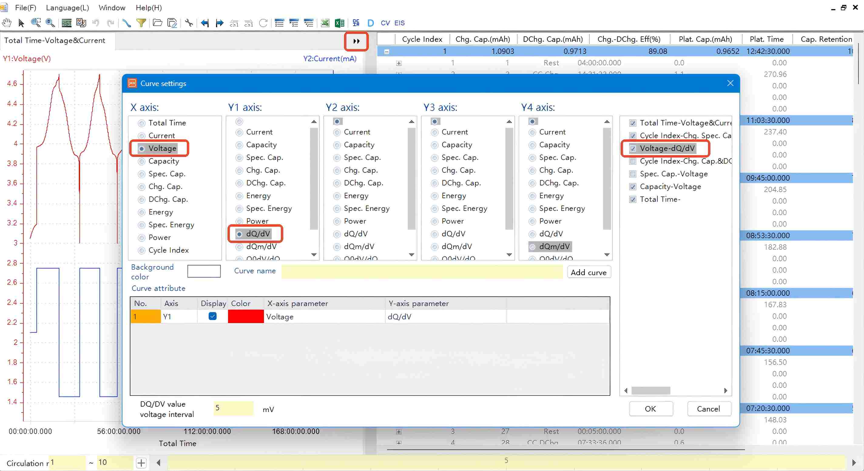
Figure 5. dQ/dV Curve Parameter Settings
In the settings dialog:
X-axis: Select "Voltage" (or "Specific Capacity")
Y1-axis: Select "dQ/dV" (or "dQm/dV", where m = active material mass)
Click "OK" to generate the dQ/dV curve.
Copy the data and paste it into Origin software to plot the corresponding dQ/dV curve graph.
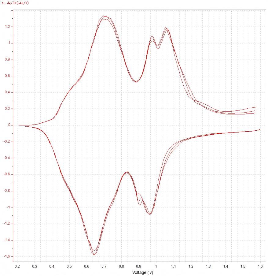
Figure 6. dQ/dV Curve
Voltage plateau identification:
"Right-click on the data plot to copy the data. After pasting into Origin and plotting, voltage plateaus can be identified from the resulting dQ/dV curve."
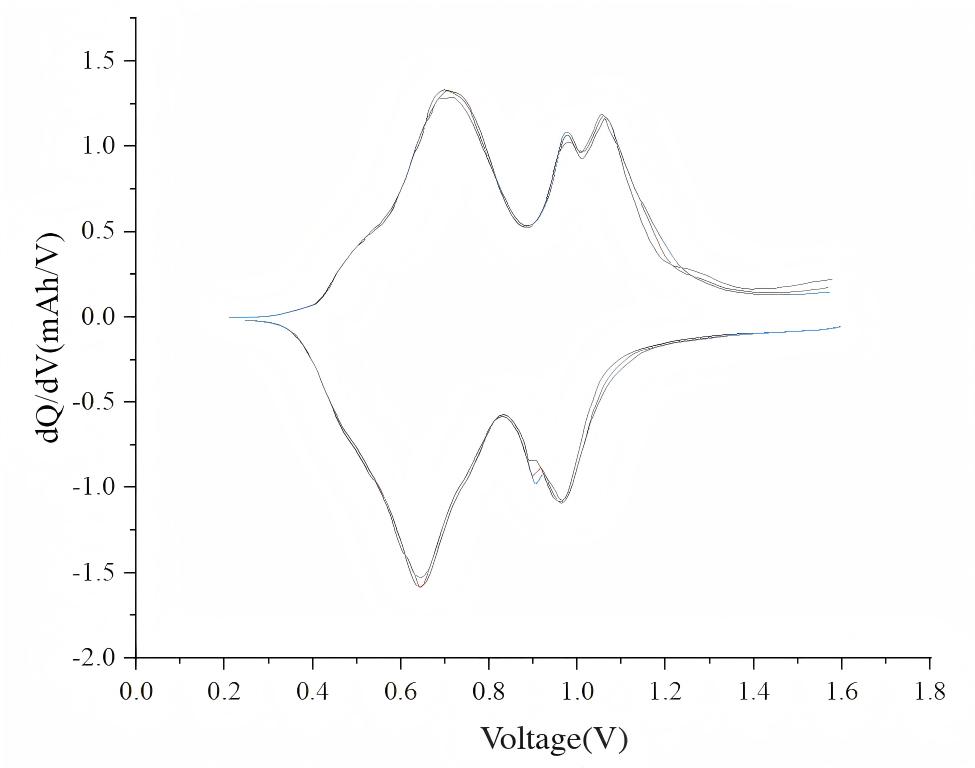
Figure 7. dQ/dV Curve Plotted in Origin
4. Application Scenarios of dQ/dV Curve Analysis
The dQ/dV curve enables non-destructive, direct identification of voltage plateaus in batteries, serving as a critical tool for investigating electrochemical performance and enhancing overall battery capabilities. Consequently, dQ/dV analysis is extensively applied in electrochemistry, particularly in battery research. Key application scenarios include:
1. Battery R&D
Used to understand electrochemical behavior of novel materials/systems and optimize battery design.
2. Performance Evaluation
Assesses key metrics: charge/discharge efficiency, energy density, power density, and cycling stability.
3. Mechanism Investigation
Reveals reaction mechanisms during charge/discharge cycles, including electrode kinetics and ion diffusion processes.
4. Failure Analysis
Diagnoses root causes of battery degradation (e.g., side reactions or structural changes).
5. Battery Management Systems (BMS)
Enables accurate monitoring/prediction of:
State of Charge (SOC)
State of Health (SOH)
Remaining useful life
6. Aging Studies
Tracks dQ/dV curve evolution during aging to study degradation mechanisms and predict lifespan.
7. Manufacturing Quality Control
Ensures product consistency and reliability during mass production.
8. Battery Recycling & Reuse
Evaluates performance of retired batteries for second-life applications.
9. Education & Training
Demonstrates battery operating principles in academic/industrial training programs.
10. Standardization
Supports development of performance benchmarks for battery technologies.
11. Environmental Impact Assessment
Evaluates performance under varying conditions (temperature, humidity, etc.).
12. Safety Testing
Analyzes behavior during abuse conditions:
Overcharge/overdischarge
Short circuit
Thermal runaway
dQ/dV testing plays a pivotal role across battery technology domains by providing granular insights into internal electrochemical processes. This methodology facilitates deeper understanding of battery mechanisms, enables design optimization, improves performance, and ensures system safety/reliability.
5. Summary
The dQ/dV testing technique constitutes an indispensable tool in battery research and development. It not only reveals complex electrochemical reactions within batteries but also empowers researchers to optimize electrode materials and cell architectures, thereby enhancing overall battery performance. Furthermore, dQ/dV analysis holds critical significance for battery health management, lifetime prediction, and safety assessment. As battery technologies advance, this methodology will continue playing a pivotal role in performance optimization and next-generation battery development.
Closing Remarks
Through this article, you have gained foundational understanding of:
dQ/dV testing principles
Parameter configuration
Data processing techniques
In upcoming installments of our Electrochemistry Series, NEWARE Team will provide in-depth explorations of battery material and design characterization methods, including:
State of Charge (SOC) Testing
DC Internal Resistance (DCIR) Measurements
EV/HEV Battery Validation Protocols
Charge/Discharge Profile Analysis


