1. Introduction
Flow batteries are a novel type of large-scale electrochemical energy storage device. When both the positive and negative electrolytes use vanadium salt solutions, it is termed an all-vanadium flow battery (VFVB), often simply called a vanadium battery. At a 100% state of charge (SOC), the open-circuit voltage (OCV) of this battery can reach 1.5 V.
A flow battery energy storage system consists of the following main components:
1. The Electrochemical Cell Stack Unit
2. The Electrolyte Solution & Electrolyte Storage/Supply Unit
3. The Control and Management Unit
The core of the flow battery system is the electrochemical cell stack. This stack is formed by connecting dozens of individual cells in series according to specific requirements. Each individual cell facilitates the redox reaction that enables the charging and discharging processes. The structure of this stack is similar to that of a fuel cell stack.
2. Working Principle of Flow Batteries
A flow battery is a novel type of rechargeable battery. It is a high-performance battery where the positive and negative electrolytes are separated and circulate independently. It features high capacity, wide applicability (across various environments), and a long cycle life, making it a new energy product. Redox flow batteries (RFBs) are a new type of large-capacity electrochemical energy storage device under active research and development. Unlike conventional batteries that use solid or gas electrodes, their active materials are flowing electrolyte solutions. Their most significant characteristic is suitability for large-scale energy storage. Given the growing demand for widespread utilization of renewable energy, it is foreseeable that flow batteries will enter a period of rapid development.
An all-vanadium flow battery (VFVB) energy storage system primarily consists of the following components:
1. Electrolyte
2. Electrochemical Cell Stack
3. Battery Management System (BMS)
4. Auxiliary Systems
The electrolyte is circulated into the cell stack system via pumps and piping. Redox reactions occur on the electrode surfaces, enabling the conversion between electrical energy and chemical energy.
The positive electrolyte consists of V⁴⁺ (vanadium(IV)) and V⁵⁺ (vanadium(V)) ion solutions.
The negative electrolyte consists of V²⁺ (vanadium(II)) and V³⁺ (vanadium(III)) ion solutions. After the redox reactions involving the different vanadium ion species occur on the electrode surfaces, the electrolytes return to their respective storage tanks.

Figure 1 Schematic Diagram of All-Vanadium Redox Flow Battery Energy
As shown in the schematic diagram (Figure 1) above:
1. The electrolyte solutions (energy storage medium) are stored in external tanks.
2. Inside the battery cell, the positive and negative compartments are separated by an ion-exchange membrane into two distinct chambers (positive side and negative side).
3. During operation, the positive and negative electrolytes are forcibly circulated by pumps through their respective reaction chambers, where they participate in the electrochemical reactions.
Charging: An external power source supplies electrical energy, which is converted into chemical energy stored in the electrolyte solutions.
Discharging: An external load is connected. The chemical energy stored in the electrolyte solutions is converted back into electrical energy to power the load.
Electrochemical Reactions:
Charging:
Positive Electrode: VO²⁺ + H₂O → VO₂⁺ + 2H⁺ + e⁻
Negative Electrode: V³⁺ + e⁻ → V²⁺
Discharging:
Positive Electrode: VO₂⁺ + 2H⁺ + e⁻ → VO²⁺ + H₂O
Negative Electrode: V²⁺ → V³⁺ + e⁻
Overall Reaction (Discharging): VO₂⁺ + 2H⁺ + V²⁺ → VO²⁺ + H₂O + V³⁺
3. Testing Instrument Overview
Cycling tests can be conducted using the Neware multi-channel battery testing system shown in Figure 2. Data can be exported directly, and results can be generated by plotting the data using Origin software.
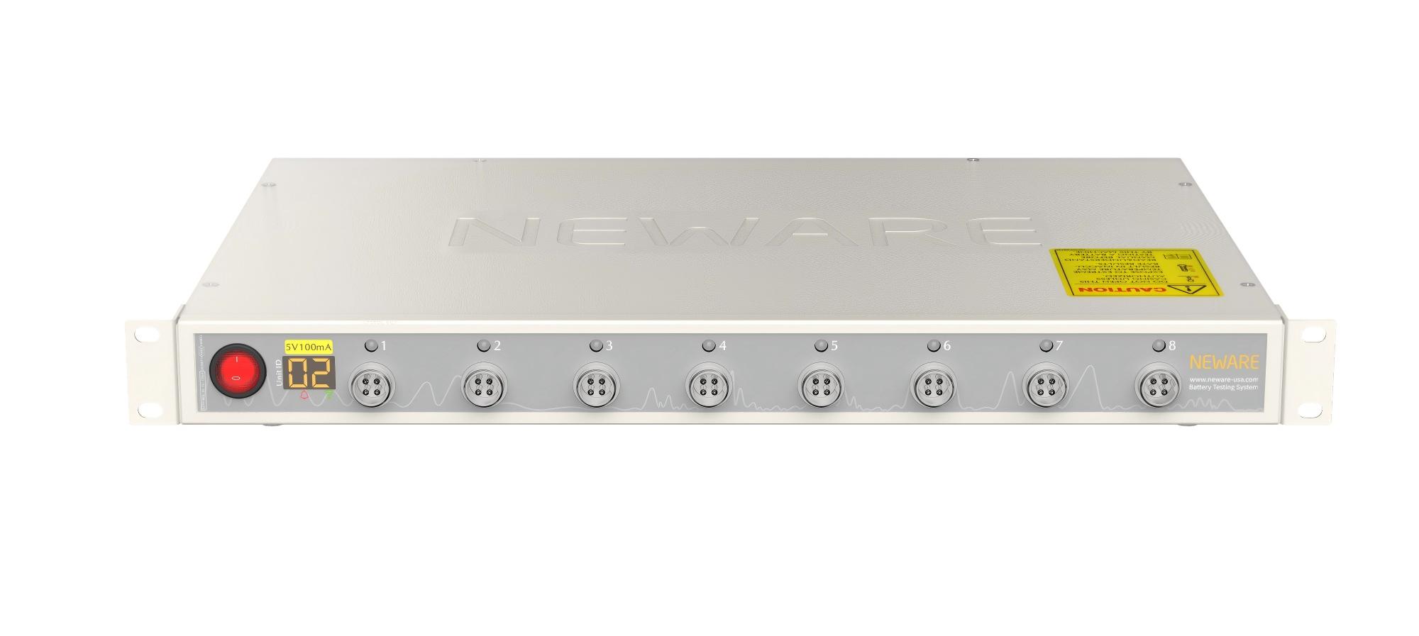
Figure 2 NEWARE Battery Testing System
(1) Charging Modes: Constant current (CC), constant voltage (CV), constant current-constant voltage (CC-CV), and constant power (CP) charging. Stop conditions include voltage, current, relative time, capacity, energy, or -△V (voltage increment).
(2) Discharging Modes: Constant current (CC), constant voltage (CV), constant current-constant voltage (CC-CV), constant power (CP), and constant resistance (CR) discharging. Stop conditions include voltage, current, relative time, capacity, or energy.
(3) Pulse Mode: Supports CC or CP charging and CC or CP discharging pulses. Minimum pulse width is 500 milliseconds. A single pulse step supports up to 32 distinct pulses and allows continuous switching between charge and discharge within one step. Stop conditions are voltage or relative time. (4) DC Internal Resistance (DCIR) Test: Supports custom point selection for DCIR calculation.
(5) Cycle Testing: Cycle range: 1~65,535 cycles; Steps per single cycle: 254. (6) Nested Cycles: Features nested looping functionality, supporting up to three levels of nesting. For more detailed test functionalities, consult Neware technical staff.
4.Parameter Configuration
Using an all-vanadium flow battery as an example: assuming a current density of 100 mA cm⁻² and an electrode area of 10 cm², the calculated current based on current density and electrode area is 1000 mA. The specific step settings are as follows:
1. Select the single-point "Initiate" mode.
2. Step 1: Set as "Constant Current (CC) Charge".
3. Step 2: Set as "Constant Current (CC) Discharge".
4. Set the current for both steps to the calculated value of "1000 mA".
5. Set the cut-off voltages as shown in the accompanying figure.

Figure 3 Specific Operation Steps
Click "Protection Conditions" to configure settings as required. Similarly, set the cycle number (loop count).

Figure 4 Protection Condition Settings
After configuring the above parameters and saving the steps, click "Start" in the bottom-right corner to commence testing.
5.Application Scenarios of Flow Batteries
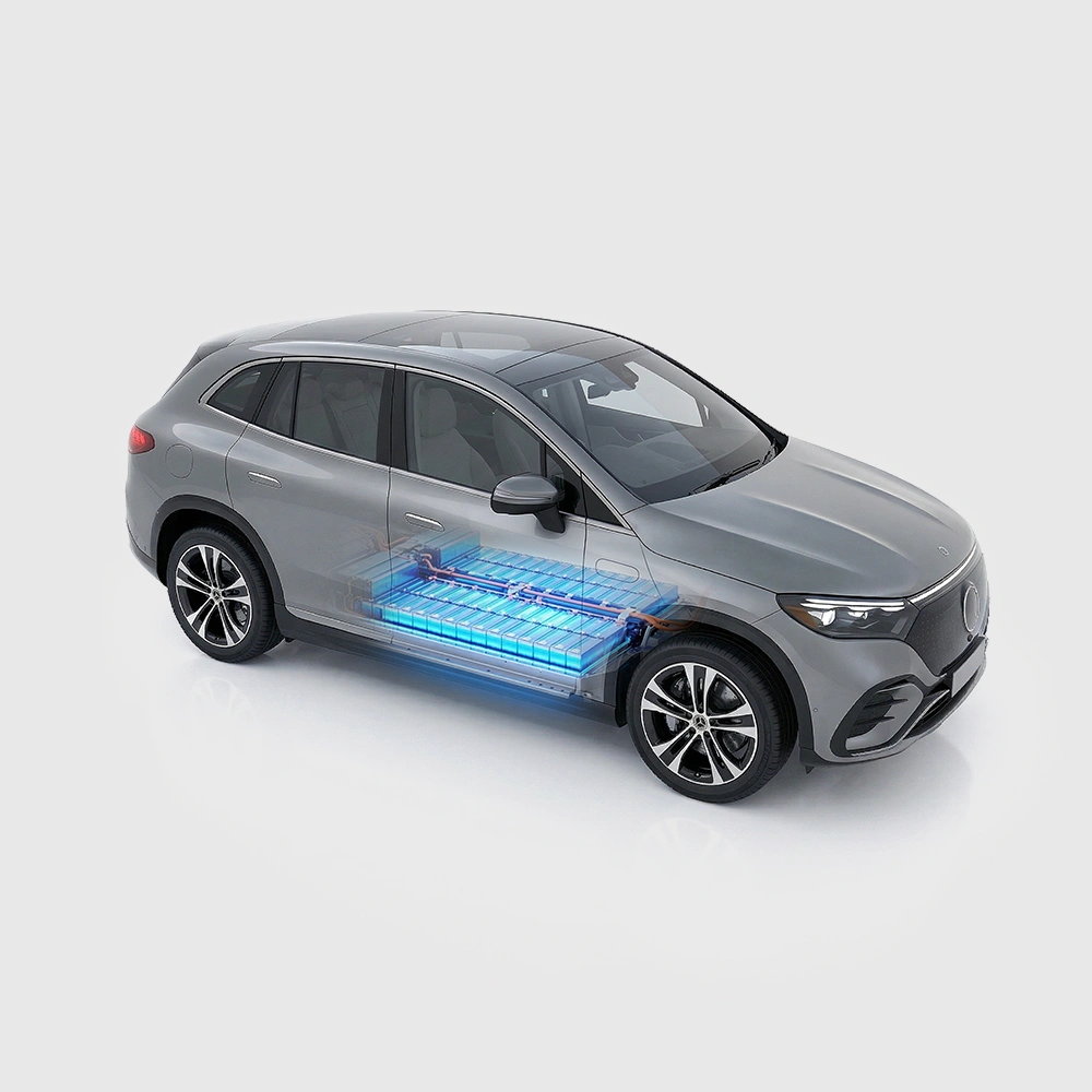
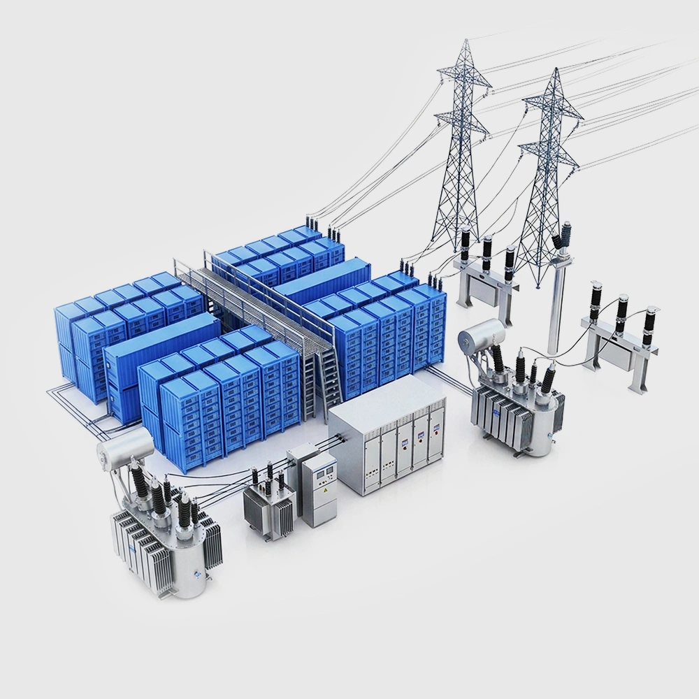
(1) Grid-Scale Long-Duration Energy Storage: Flow batteries, leveraging their advantages in long-duration storage capability and high safety, play a vital role in grid peak shaving, frequency regulation, and integration of distributed energy resources. For instance, at wind farms and solar power stations, flow battery energy storage systems can effectively store surplus electricity and release it during periods of insufficient energy supply. This enables stable power output, reducing grid instability.
(2) Renewable Energy Grid Integration Storage: Flow batteries are widely deployed in the field of renewable energy grid integration storage. Particularly for renewable power generation like wind and solar energy, they store excess electricity and discharge it when supply is inadequate, thereby increasing the utilization rate of renewable energy.
(3) Smart Grid Development: In smart grid development, flow batteries provide stable power supply. Specifically:
- During peak grid load periods, they release stored energy to meet user demand.
During low-load (valley) periods, they charge, helping to balance grid supply and demand.
(4) Off-Grid Power Supply for Islands & Remote Areas: Due to their strong environmental adaptability and simple maintenance requirements, flow batteries serve as an ideal choice for off-grid power systems on islands and in remote regions. In these areas, they provide reliable power security, especially where grid coverage is unavailable.
(5) Backup Power Supply: Flow batteries, characterized by high safety and long cycle life, are strong contenders in the backup power sector. They can deliver stable and reliable power support for new infrastructure such as 5G base stations and data centers, ensuring their normal operation during emergencies.
(6) Industrial User-Side Energy Storage: In industrial settings, particularly in steel and chemical production, flow batteries are extensively utilized due to their high safety and corrosion resistance. They store electricity during low-demand (valley) periods and discharge during high-demand (peak) periods. This peak shaving and valley filling effectively balances electricity load and reduces corporate electricity costs.
These application scenarios demonstrate the broad potential of flow batteries across multiple sectors, particularly in situations demanding high safety, long lifespan, and large capacity