1. Introduction
Hybrid Pulse Power Characterization (HPPC) testing is a method used to characterize the pulse charge/discharge performance of power batteries. It is a crucial testing methodology within power battery performance evaluation, primarily targeting performance assessment and power system management for hybrid electric vehicle (HEV) battery systems, modules, and individual cells.
2. The testing principle of HPPC
HPPC testing is typically conducted using specialized battery testing equipment. Its ultimate purpose is to validate the calculation of pulse power capability, available energy, and available power, providing a reasonable assessment of the power discharge capability for HEV-type applications (this methodology has now been extended to PEVs within China).
The characteristic HPPC test profile is illustrated in Figure 1(a). The goal of this profile is to demonstrate the discharge pulse power capability and regenerative charge pulse power capability of the power-assist targets at various depths-of-discharge (DOD). The HPPC test procedure essentially consists of repeating the profile shown in Figure 1(a).
The test commences from a fully charged state. After discharging the battery by 10% DOD, it is allowed to rest for 1 hour, followed by the application of the pulse profile. This cycle – discharging 10% DOD, resting for 1 hour, and applying the pulse profile – is repeated until the battery reaches 100% DOD. After the final discharge to 100% DOD, a final 1-hour rest period concludes the test, as depicted in Figure 1(b). The 1-hour rest period is crucial to allow the battery to reach electrochemical and thermal equilibrium.
The voltage during each rest period must be recorded to establish the battery's Open-Circuit Voltage (OCV) curve. The test pulses utilize two peak current levels: a low current (25% of Imax) and a high current (75% of Imax). Imax refers to the maximum allowable 10-second pulse discharge current specified by the battery manufacturer.

Figure 1
Note: The OCV voltage is measured during the rest period.
Fundamentally, an HPPC pulse test is performed at every 10% DOD interval, progressing from high SOC to low SOC. The interval can also be made smaller based on system design requirements, resulting in a denser data table. It's important to note that each discharge step is followed by a 1-hour rest period. This waiting time allows the battery voltage to return to a near-resting state. However, in practice, 1 hour is often insufficient for the battery to reach a state of absolute static equilibrium. Consequently, using the voltage measured at the end of this rest period to plot the SOC-OCV curve yields only a reference curve, not the curve representing the true absolute equilibrium state.
HPPC Test Result Analysis includes the following aspects:
1. Open-Circuit Voltage (OCV): The voltage measured at the end of each HPPC rest period. This can be plotted as a function of DOD.
2. Internal Resistance Characteristics: Based on the test data, the discharge resistance and regenerative charge resistance are calculated. These resistances vary with DOD.
○ Pulse Power Capability: Derived from the voltage and resistance characteristics. This can be plotted as a function of DOD and includes:
■ Discharge Capability
■ Regenerative Charge Capability
3. Available Energy: Defined as the energy obtainable from the battery system under a 1C discharge rate. It is determined by establishing the relationship between power and the energy delivered by a 1C discharge at various DOD points.
4. Available Power: The maximum discharge power capability when the available energy reaches a specific target value.
5. Power and Energy Degradation (or Fade): Refers to the change in available power and available energy over time during system life testing.
3. The Parameter Settings of HPPC
HPPC Testing Implementation:
The HPPC test can be performed using a NEWARE multi-channel battery testing system, as shown in Figure 2. The exported data is subsequently processed using Origin software to generate the results.
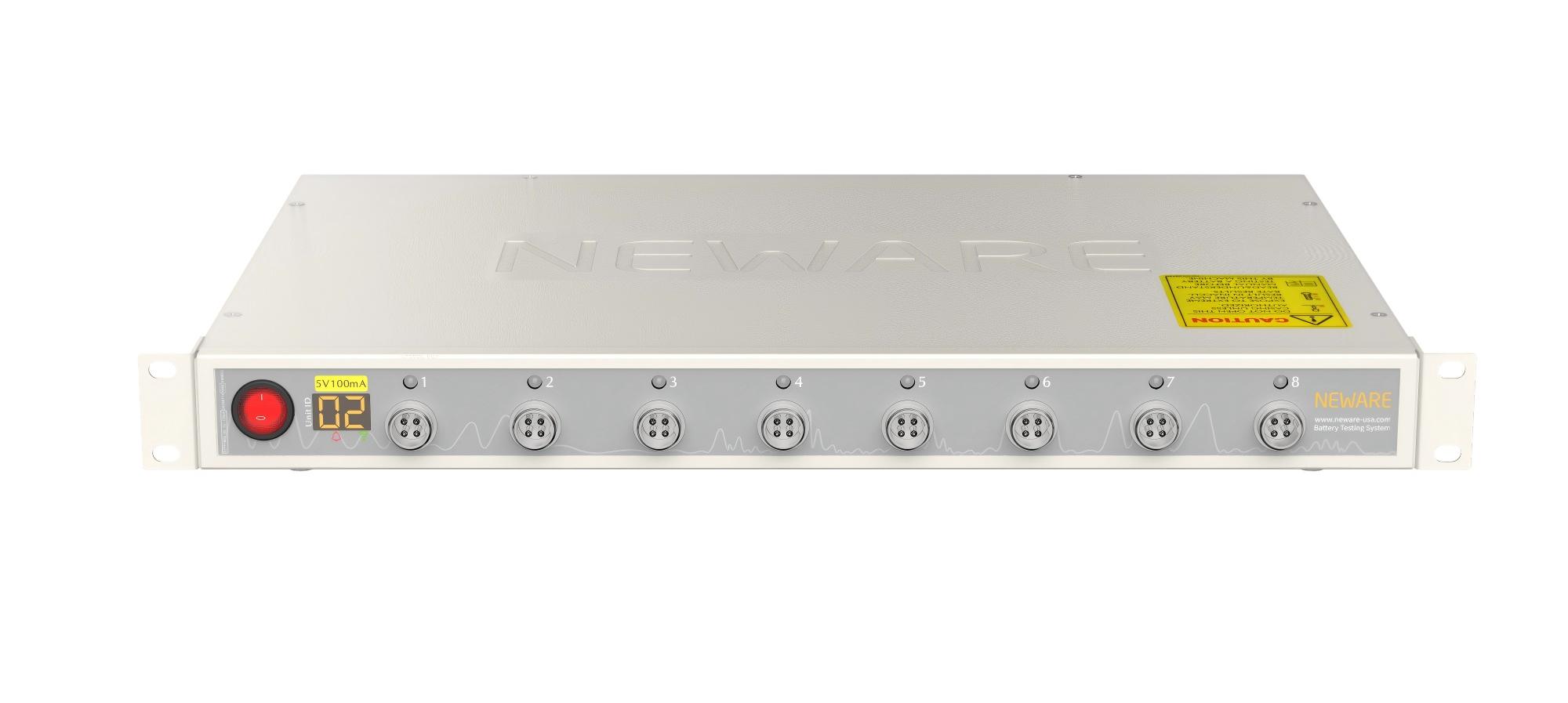
Figure 2: NEWARE Battery Testing System
(1) Charging Modes: Constant current (CC), constant voltage (CV), constant current-constant voltage (CC-CV), and constant power (CP) charging. Stop conditions include voltage, current, relative time, capacity, energy, or -△V (voltage increment).
(2) Discharging Modes: Constant current (CC), constant voltage (CV), constant current-constant voltage (CC-CV), constant power (CP), and constant resistance (CR) discharging. Stop conditions include voltage, current, relative time, capacity, or energy.
(3) Pulse Mode: Supports CC or CP charging and CC or CP discharging pulses. Minimum pulse width is 500 milliseconds. A single pulse step supports up to 32 distinct pulses and allows continuous switching between charge and discharge within one step. Stop conditions are voltage or relative time.
(4) DC Internal Resistance (DCIR) Test: Supports custom point selection for DCIR calculation.
(5) Cycle Testing: Cycle range: 1~65,535 cycles; Steps per single cycle: 254.
(6) Nested Cycles: Features nested looping functionality, supporting up to three levels of nesting. For more detailed test functionalities, consult Neware technical staff.
Parameter Settings (Lithium-ion Battery Example):
Based on the principles of HPPC, the following test steps (work steps) are configured. The specific voltage and current parameters should be set according to the actual requirements of the test.

Figure 3: Specific Test Step Configuration
The figure illustrates setting an expression to record the discharge capacity. To record the charge capacity instead, the corresponding expression should be set within the charge step. The specific expressions for Step 8 and Step 13 are shown in the figure below:

Figure 4: Expression for Test Step 8

Figure 5: Expression for Test Step 13
Within these expressions, the value 0.1 represents a 10% capacity fade, and 0.8 represents an 80% capacity fade.
4. Application Scenarios
1. Hybrid Electric Vehicle (HEV) Battery System Performance Evaluation: HPPC testing evaluates the power performance and durability of battery systems for hybrid electric vehicles, aiding in understanding and optimizing real-world battery behavior.
2. Battery Module and Cell Evaluation: Performing HPPC tests on battery modules and individual cells enables precise measurement of their power output and charging efficiency at various depths-of-discharge (DOD), which is crucial for battery design and optimization.
3. Guiding Battery Management System (BMS) Design: Data from HPPC testing helps Battery Management Systems (BMS) more effectively monitor and control battery states, ensuring safe and economical operation. Furthermore, HPPC testing provides a better understanding of battery performance under diverse operating conditions, enabling more accurate state estimation for EV BMS. Accurate BMS state estimation relies on suitable battery models and precise model parameters, for which HPPC testing supplies the necessary data.
4. Battery State Estimation: HPPC testing facilitates a deeper understanding of battery performance across different operating conditions, providing vital data for the design and optimization of electric vehicles.
5. Powertrain Design and Battery Life Management: HPPC test results are used to determine battery power-assist targets and assess discharge pulse power capability and regenerative charge pulse power capability at different DOD levels. This is highly significant for electric vehicle powertrain design and battery life management.
6. Battery Performance Assessment: By simulating pulse charge/discharge processes at various states of charge (SOC), HPPC testing evaluates key battery characteristics such as power performance, open-circuit voltage (OCV), and DC internal resistance (DCIR). The test involves cycling the battery from a fully charged state to full discharge. After every 10% DOD discharge increment, the battery rests for 1 hour followed by a pulse test. This cycle repeats until reaching 100% DOD, concluding with a final 1-hour rest period.
7. Analyzing Battery State: During testing, the DC internal resistance in both charge and discharge directions at various SOC points, along with the battery's open-circuit voltage, can be measured. This data is essential for understanding battery performance under different operating conditions and provides critical information for EV design and optimization.
8. Predicting Battery Lifetime: HPPC testing helps determine battery power-assist targets and evaluate discharge pulse power capability and regenerative charge pulse power capability at different DOD levels. This is paramount for electric vehicle powertrain design and battery life management.
These application scenarios demonstrate that HPPC testing is an indispensable part of power battery technology research and product development.
5. Conclusion
In summary, HPPC testing is a critical methodology. It not only aids in evaluating and optimizing battery performance but also provides essential data support for electric vehicle design and Battery Management System (BMS) development. Through this introduction, we trust you have gained an understanding of parameter settings and calculation method modifications for DCIR-P under standard test steps. In upcoming articles within our electrochemistry series, the NEWARE team will provide detailed insights into electrochemical testing related to battery materials and design, such as nested cycling, step charging, and constant resistance discharge. We welcome your attention, sharing, and support for our work.