Part 1: Device wiring
1.1 Hardware connection
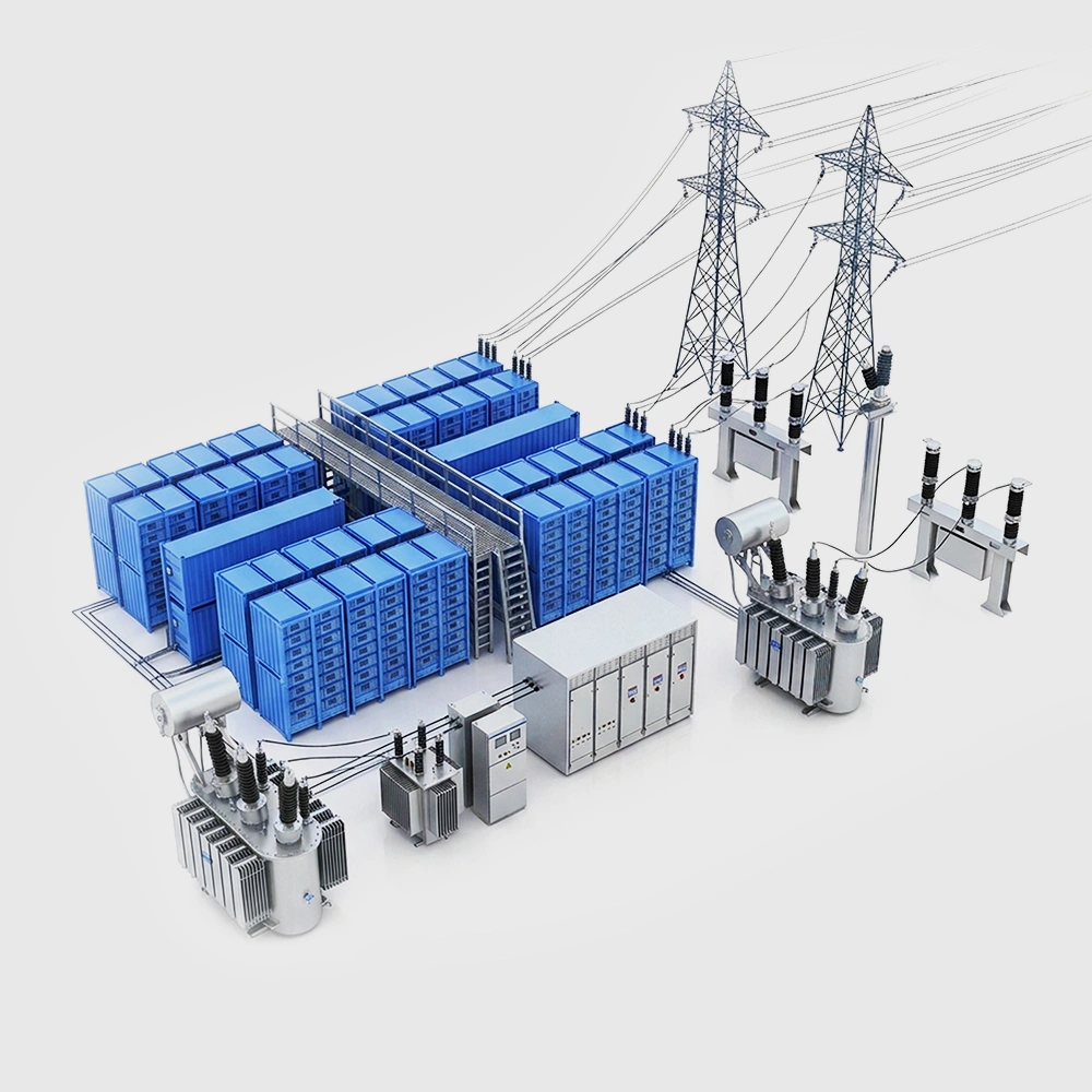
1. Connect each device to a switch using Ethernet cables.
2. Also connect the switch to a computer with an Ethernet cable.
3. Power on the devices after connecting their three-wire power cords to a power source.

Figure 1: Device wiring diagram
1.2 Basic device information
1. Device front

Figure 2: Single device front view
Item | Name | Description |
1 | Power Switch | Toggle to start the device |
2 | Device Number Display | Shows the device channel number |
3 | Channel Status Light | Green for charging, red for discharging, yellow for idling (customizable) |
2. Device back

Figure 3: Device rear view
Item | Name | Description |
1 | D-Sub Connector | For current and voltage connections |
2 | SMBUS Communication Port | Interfaces with the battery communication system |
3 | Power Cord Socket | 110V AC (For other requirements, please contact the sales manager) |
4 | TCP/IP Port | Connects to a PC via Ethernet cable |
5 | Thermocouple Socket | Compatible with T-type, K-type thermocouples for temperature measurement |
6 | Fan Exhaust | Aids in device cooling |
Part 2: Software setup
2.1 New installation
1. Installation options:
Standard installation: Follow the on-screen defaults without selecting specific modules.
Customized installation: Pick and choose modules like client, server, backup server, and report server. Set the installation directory and select the language (Chinese/English).
2. Important notes:
The BTS 9.1 software is compatible only with the NTFS file system.
Before installation, disable the Windows Firewall or allow access through TCP ports 8002, 8003, and 8004.

Figure 4 Computer system interface
3. Recommended hardware configurations
Device | Configuration |
CPU | Intel(R) Core(TM) i3-9100 CPU @ 3.60GHz |
Host frequency | 3.6 GHz |
Memory | 16.0 GB (15.8 GB Available) |
System disk | SATA interface, 500G or more |
File system | NTFS |
Operating system | Microsoft Windows 10 64-bit or above |
Interface | Ethernet port, RS232/485 |
Graphics card | Intel(R) UHD Graphics 630 |
Switch | Huawei H3C switch (Cisco recommended) |
Power supply | UPS (Inventor HT11 recommended) |
4. Installation procedure:
Unzip the client software file and right-click to “Run as Administrator.”
Select your preferred language and follow the on-screen instructions.
2.2 Upgrading the software
1. Users can directly upgrade if the older version is compatible with the new one. If not, uninstall the existing software first and then install the new version.
2. Upgrade steps:
After selecting the language, you’ll land on the “Installed Version Check” page showing the current software version and installation path.
Click “Next.” On the “Upgrade Options” page, choose the upgrade mode and content as needed. The default upgrade mode is in the original directory, and the default upgrade content includes the client and server. Click “Next” again, review the warning message, and start the upgrade.
Before upgrading the server, make sure all channels connected to it are stopped. If not, halt or pause the test. Also, ensure all channels have been stopped for over 20 minutes.
Before upgrading the client, close all related client software (Neware_BTS9_Client, BTSDA, BuildTest) and related files opened by other software, such as log files.
Prior to upgrading the backup server, shut down all backup-related software (Neware_BTS9_Backup) and related files opened by other software.
Click “Finish” to exit the installation wizard. The software upgrade is now complete.
Part 3 Software interface walkthrough
3.1 Main page
After the software has been successfully downloaded and installed, commencement of use begins with user authentication. Input the username as "admin" and the password as "xinwei" to log in. This login process is a prerequisite for accessing additional functions and features.

Figure 5 BTS 9.0 main interface
(1) Setup button: Click to enter the setup interface;
(2) Operate channel control;
(3) Channel copy: Copy the current channel steps and paste them into other channels;
(4) Historical data: View the channel's testing records;
(5) DBC information: View data from the battery communication board;
(6) Report export: Manually export reports;
(7) Open data: Open the BTSDA data analysis software to view data records.The client offers three display modes for channels: Large Icon, Small Icon, and List. You can switch modes by clicking the icon or accessing the dropdown menu.
Once the device is successfully connected, it and its channels will be displayed on the client automatically. If not, check the device connection.

Figure 6 Device and channel interface
The client channel display has three modes: Large Icon, Small Icon, and List. Click the "box" icon or its dropdown menu to switch modes.
 Figure 7 Switch display mode
3.2 Client configuration adjustment
Click the gear icon to access the client configuration page.

Figure 8 Enter system settings
You can configure barcode input and calibration settings here. Modify the values as needed. You can also set the channel status display colors, which will reflect on the client channels based on the configuration. After making changes, click “Confirm” and “Save.” This page also allows modifications to “Default Step Protection Parameters.” Double-click the table to edit the values. Similarly, you can adjust units, data download paths, and more.

Figure 9 Client configuration interface
3.3 Starting a test
Left-click to select the channel for testing. A yellow border indicates the channel is selected. To select multiple non-consecutive channels, hold the Ctrl key and click the desired channels. Use Ctrl+A to select all channels. Then right-click and choose “Start.” Enter the step settings page, configure the parameters as needed, and click the “Start” button at the bottom-right corner to begin the test.

Figure 10 Start testing

Figure 11 Step editing
3.4 Exporting reports
After completing the test, right-click on the channel with the data to export and select “Export Report.” On the “Cycle Layer Export” or “Step Layer Export” page, choose the data items to export, such as cycle number, voltage, current, charge/discharge capacity, and specific capacity. You can also customize the unit, numerical format, background color, font color, bold option, and alignment style for the data items.


Figure 12 Manually export reports
3.5 User management
3.5.1 User login
Logging in: You must log in to perform user management tasks. The default username is “admin” and the password is “xinwei.” You can check “Remember Password” and “Auto-Login” for convenience.

Figure 13 User login
3.5.2 Permission management
Managing permissions: You can create, modify, or delete user groups and define their operational permissions.

Figure 14 User managements
Part 4. BTSDA data analysis
4.1 Viewing data
1. To view data, right-click on the desired channel and select “Open Data,” or directly open the saved BTSDA data file.

Figure 15 View data
4.2 Introduction to BTSDA
Right-click and select "Open Data" (as shown in Figure 15) to access the BTSDA page. Click the table icon at the top to export reports, and choose the desired report type based on your needs.

Figure 16 Export reports
Right-click in the table area and select "Parameter Settings" to modify the "Cycle Statistics Method" according to your requirements, such as changing it to "Charge First, Then Discharge" or "Discharge First, Then Charge."

Figure 17 Parameter setting interface
Click the pentagram icon at the top of the graph area to adjust the curve settings. You can select parameters for the X-axis and Y-axis, add new labels, and confirm the changes.

Figure 18 Curve setting